


Classification
3 - B (Evaluation technology for IASCC)
In order to maintain and enhance safety of light water reactors (LWRs) in long-term and up-graded operations, proper understanding of irradiation behavior of fuels and materials is essentially important. Japan Materials Testing Reactor (JMTR) of Japan Atomic Energy Agency (JAEA) has been used for fuels and materials irradiation studies. For the study on the effects of irradiation field in reactor core on the irradiation-assisted stress corrosion cracking (IASCC) (Fig. 1), the in-pile IASCC growth and initiation tests had been performed in the JMTR [1, 2]. The differences between the in-pile test and post irradiation experiment (PIE) on IASCC are listed in Table 1. The operation of the JMTR was stopped in 2006 for the refurbishment and will restart in 2011 [3, 4].
The JAEA has planned to install new test rigs in the JMTR during the refurbishment for solving irradiation related issues on the plant aging and the extended uses of the LWRs supported by the Nuclear and Industrial Safety Agency (NISA) of the Ministry of Economy, Trade and Industry (METI) [5]. For the safety research on the IASCC behavior of the boiling water reactor (BWR) core internals such as the core shroud, the water loop system for simulation of the BWR water conditions is being installed in the JMTR. In addition, in order to understand the effects of irradiation field on the IASCC growth behavior, new test rigs are being developed for in-pile IASCC growth tests, which are planned from 2013 to 2016 [6, 7].
The new in-pile IASCC growth test rigs can treat a compact tension specimen with thickness of 0.5 inches (0.5T-CT), which is larger and thicker than the specimens used for the former in-pile IASCC growth tests [2, 8]. For use of the 0.5T-CT specimen within the limitation of inner diameter of the irradiation capsule in the JMTR, modification of the design of the loading unit and the detecting system of crack length of the specimen by the potential drop method (PDM) has been performed. Moreover, in the irradiation capsule, water chemistry under irradiation can be evaluated by measuring the electrochemical corrosion potential (ECP) of the test materials during in-pile IASCC growth tests. For the in-pile ECP measurement, the ECP sensor (reference electrode) has been modified to have a robust structure toward irradiation as well as thermal cycle.
The new in-pile test rigs can contribute to improvement of the evaluation technology for the IASCC growth behavior of irradiated materials.
Table 1 Differences between in-pile test and PIE on IASCC
|
In-pile test |
PIE |
Water chemistry |
Radiolysis effects can be detected directly. |
Radiolysis effects are simulated by controlling the dissolved oxygen concentration. |
Material properties |
Dynamic changes as well as accumulative changes by irradiation can be simulated. |
Only accumulative changes by irradiation are simulated. |
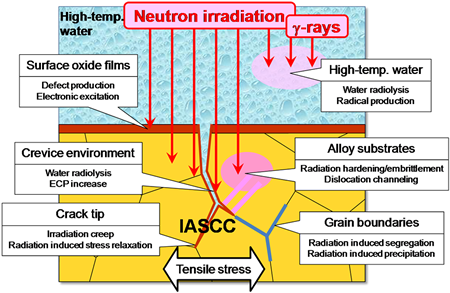
Fig. 1 Irradiation effects related to IASCC in reactor core
Phase 1 : Research and Development Phase
- Prototype test rigs have been developed.
- New in-pile crack growth test rig can treat a 0.5T-CT specimen with 12.7 mm thick, although the specimen size has been limited to 0.4T-CT with 5.6 mm thick in the former in-pile IASCC growth tests.
- The crack growth of the 0.5T-CT specimen loaded up to ~7 kN (corresponding to K~30 MPa√m) is monitored by the PDM in the irradiation capsule of the JMTR. The ECP is measured during the tests.
- - Modification of the design of the loading unit and the detecting system of crack length of the specimen by the PDM can lead to use the 0.5T-CT specimen within the limitation of inner diameter (44 mmΦ) of the irradiation capsule in the JMTR.
- The water loop system for simulation of the BWR water condition is shown in Fig. 2. The test rig for loading the specimen, a ZrO2 membrane type ECP sensor (reference electrode) with Fe/Fe3O4 electrode and brazing sealing, and a layout of those are shown in Figs. 3, 4 and 5, respectively.
- Lever-type loading unit using bellows, which generates load by controlling the difference between inner gas pressure and surrounding water pressure.
- PDM measurement using mineral insulator (MI) cable.
- Specimen with "the Wing", which facilitate a connection between irradiated specimen and MI cable in hot cell.
- Two test rigs can be arranged in an irradiation capsule.
- The corrosive atmosphere in the test section is planned to be monitored by the ECP sensors, in order to have better understanding on the radiolysis effects.
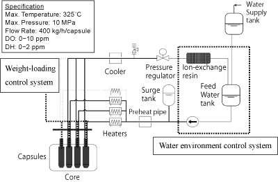
Fig. 2 Water loop system for simulation of BWR water condition in JMTR
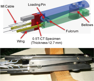
Fig. 3 Schematic drawing and photo of prototype in-pile crack growth test rig
(lever ratio 1:6)
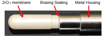
Fig. 4 Overview of ZrO2 membrane type ECP sensor
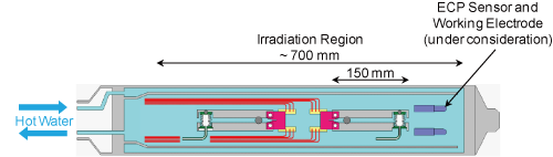
Fig. 5 Schematic layout of test rigs and sensors in an irradiation capsule
Basic functional tests using prototype test rigs have been performed under unirradiation condition.
- Evaluation of IASCC growth rates under irradiation field for the BWR core shroud
- - Dependence of fast neutron fluence, stress intensity factor and ECP of the test material on crack growth rates
- Evaluation of ECP of materials under irradiation field in the BWR core region
- [1]H. Ugachi, Y. Kaji, J. Nakano, et al., "Development of Test Techniques for In-pile SCC Initiation and Growth Tests and the Current Status of In-pile Testing at JMTR", Proc. 12th Int. Conf. Environmental Degradation of Materials In Nuclear Power System – Water Reactors –, TMS (2005) 319-325.
- [2]Y. Kaji, H. Ugachi, T. Tsukada, et al., "In-Core SCC Growth Behavior of Type 304 Stainless Steel in BWR Simulated High-Temperature Water at JMTR", J. Nucl. Sci. Technol. 45 (2008) 725-734.
- [3]H. Kawamura, M. Niimi, M. Ishihara, et al., "Status and Future Plan of Japan Materials Testing Reactor", JAEA-Conf 2008-011 (2009) 48-52.
- [4]M. Kaminaga, M. Niimi, N. Hori, et al., "Current Status of JMTR Refurbishment Project", JAEA-Review 2009-056 (2010).
- [5]T. Nakamura, Y. Nishiyama, Y. Chimi, et al., "New JMTR Irradiation Test Plan on Fuels and Materials", Proc. 16th Pacific Basin Nuclear Conf. (16PBNC), Oct. 13-18, 2008, Aomori, Japan, P16P1117, (2008).
- [6]Neutron Irradiation and Testing Reactor Center, "Annual Report of the Neutron Irradiation and Testing Reactor Center FY 2007 (April 1, 2007-March 31, 2008)", JAEA-Review 2008-082 (2009).
- [7]Neutron Irradiation and Testing Reactor Center, "Annual Report of the Neutron Irradiation and Testing Reactor Center FY 2008 (April 1, 2008-March 31, 2009)", JAEA-Review 2009-037 (2009).
- [8]T.M. Karlsen, P. Bennett, N.W. Høgberg, "In-Core Crack Growth Rate Studies on Irradiated Austenitic Stainless Steels in BWR and PWR Conditions in the Halden Reactor", Proc. 12th Int. Conf. Environmental Degradation of Materials In Nuclear Power System – Water Reactors –, TMS (2005) 337-348.
Japan Society of Maintenology (ejam@jsm.or.jp)