


| Vol.2 No.3 |
| General Articles |
| Vol.2, No.4, GA15 |
|
|
Shinro Hirano1, Kenichi Hamasaki1, and Koji Okimura2
1 Nuclear Power Division, the Kansai Electric Power Co.,Inc 2 Kobe Shipyard & Machinery Works, Mitsubishi Heavy Industries, Ltd. |
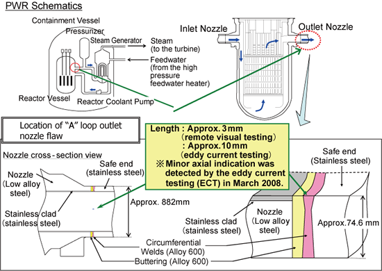
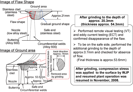
1. IntroductionRegarding the PWSCC issue of Alloy 600, general activities for PWSCC are discussed in "Maintenance Activity for Alloy 600 in PWR Plants <Part 1>," and activities to repair SG nozzles and pressurizer nozzles are discussed in the last issue "Maintenance Activity for Alloy 600 in PWR Plants <Part2>" [1][2]. In this paper, we introduce activities and cases on repair and planned maintenance in response to Ohi Unit 3 RV outlet nozzle weld defects. 2. Defect found in the RV Outlet NozzleAs stated in <Part 1>, there are some cases of defective welds in the RV outlet nozzle in various countries such as the United States. Degradation of domestic PWR plants have been mitigated by the surface residual stresses improvement via water jet peeing (WJP). Prior to implementation of WJP, eddy current testing (ECT) had been performed to determine the integrity of the surface to be subject to WJP. In March 2008, ECT detected a significant axial indication on the reactor vessel "A" loop outlet nozzle welds of Ohi Unit 3 before implementation of the WJP, and the visual testing (VT) using the underwater camera detected a 3mm length flaw. As a test result, the crack grew in the direction of depth along with the metal boundary in the welds, and a trace of machining that causes tensile residual stress on the inner surface was detected. Since the crack has similar features of SCCs detected in Alloy 600 welds in other plants, it was assumed the PWSCC developed and grew in that area (See Figure 1). The defect was completely removed by grinding the area to the depth of approximately 21mm. The evaluation ensured that the area had a sufficient thickness, and had no effect on plant operation even under the condition with local dents, and did not cause any safety problems after grinding, then the residual stress improvement was performed on the surface by WJP and plant operation was resumed in November 2008 (See Figure 2).
Figure 1 Location of Flaw in Ohi Unit 3 Reactor Vessel Nozzle Welds
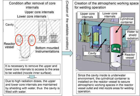
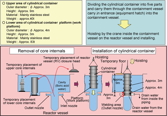
Figure 2 Flaw Handling Condition in Ohi Unit 3 (as of November 2008) 3. Development of Inlay Welding Repair at Outlet NozzleAfter removal of the defect, the RV "A" loop outlet nozzle in Ohi Unit 3 was determined to have sufficient thickness under that condition with a partial dent by the strength evaluation, however, the area was scheduled to be backfilled by welding. Since the area is normally submerged under water, a technique to install a cylindrical container in the reactor vessel to secure atmospheric working space inside outlet nozzle was developed (See Figure 3).
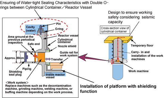
Figure 3 Method Outline using Cylindrical Container The cylindrical container is approx. 12 meters in length, and approx. 3 to 4 meters in diameter, has a total weight of approx. 120 tons, and consists of several parts. The cylindrical container was designed such that double O rings were provided to ensure sealing between each step of cylinder and between the cylinder and reactor vessel, and to take seismic capacity into consideration. Furthermore, the vertical ladder and elevator were installed for up and down movement in the cylindrical vessel for safety of working personnel, reduction of radiation exposure, and convenience (See Figure 4 and Figure 5).
Figure 4 Method Outline Using Cylindrical Container
Figure 5 Cylindrical Container Structural Schematic Although the low alloy steel nozzle material requires post-weld heat treatment, in this time, the structure reason in order to be not access does not allow implementation of the heat treatment, thus, the ambient temperature temper bead welding technique that does not require post-weld heat treatment has been developed. (See Figure 6) 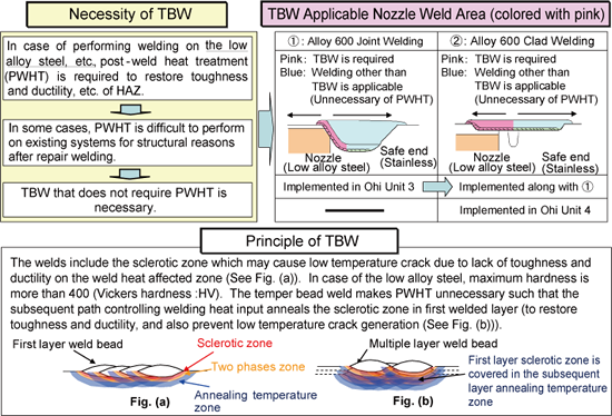
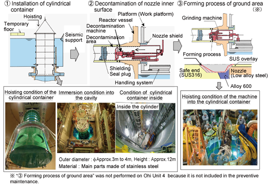
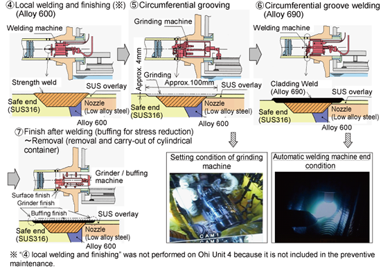
Figure 6 Outline of Temper Bead Welding Technique (TBW) and Applicable Nozzle Weld Range Based on the above-mentioned development and verification, the backfill of the area by welding was implemented in October 2009, after one cycle operation. Additionally, the clad welding with Alloy 690 having high PWSCC resistance was performed after grinding of the whole circumferential inner surface of the welds to isolate the Alloy 600 environmentally from the reactor coolant. (See Figure 7 and Figure 8) After installing the cylindrical container in the reactor vessel, the decontamination of nozzle inner surface for contamination reduction, Excavation for Alloy 600 weld by mashing, clad welding by Alloy 690, surface finishing, and welding part inspection (PT, UT).
Figure 7 Actual Working Condition (Inlay Welding Repair in Ohi Unit 3)(1/2)
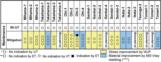
Figure 8 Actual Working Condition (Inlay Welding Repair in Ohi Unit 3) (2/2) 4. RV Outlet and Inlet Nozzles Maintenance ConditionsKansai Electric Power Co., Inc. determined to perform, after implementation of the weld repair in the Ohi Unit 3, the planned preventive maintenance on plants without being subject to the WJP to environmentally isolate Alloy 600 from the reactor coolant by inlay welding with Alloy 690. The anti-PWSCC measures are sequentially underway, and the reliability improvement has been performed by the planned preventive maintenance at the end of 2010 year (See Figure 9).
Figure 9 Preventive Maintenance Record of Reactor Vessel Outlet 5. SummaryWe described preventive measures and activities for PWSCC, defect experiences of domestic plants, and repair and preventive maintenance. As for the anti-PWSCC measures, we developed the stress improvement technique by means of WJP, etc. and the weld repair technique such as the method using a cylindrical container, etc. and have conducted the preventive maintenance on the actual system as planned. MHI continues to promote development of preventive maintenance techniques and repair techniques in cooperation with utilities based on lessons learned from domestic and abroad defect cases and implements the maintenance of each system to improve reliability further and secure safe operation of domestic PWR plants. Reference
|
|
Vol.10 No.2(Aug) |
|
| < Other Issues | |
|---|---|
 |
A New Mechanical Condition-based Maintenance Technology Using Instrumented Indentation Technique |
 |
Survey robots for Fukushima Daiichi Nuclear Power Plant |

Contacts
(EJAM): ejam@jsm.or.jp
(JSM): secretariat@jsm.or.jp
HP: http://www.jsm.or.jp
(in English)
![]()