


Classification
4 - A (Maintenance Technology for Replacement of Main Control Boards)
Ikata Unit 1 and 2 started commercial operation in September 1977 and in March 1982, respectively. The motivation behind the CBR (Control Board Replacement) project was the following: procurement of replacement parts and components is becoming difficult these days due to the supply stop; digital control systems are now widely used; partial replacement of equipment can be very costly because of complexity associated with connecting systems; the decision was made to replace the entire I & C (Instrumentation and Control) systems, including the main control boards, safety protection systems, reactor control systems, and cabling between different devices, with integrated digital systems incorporating state-of-the art technologies.
Prior to the implementation of the CBR project, the comprehensive review was performed on the reliability of the work, the operability of power supply systems, and the economics, for Units 1 and 2 were shutdown for a refueling outage almost at the same time. As a result, the replacement construction was able to be completed in about four months.
Phase 3 : Publicly-accepted Phase
3.1 Overall architecture of the equipment
The overall architecture of the equipment included in the project scope is shown in Figure 1.
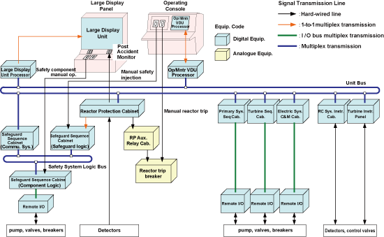
Fig. 1 Overall architecture of the equipment within the project scope
3.2 Advance preparations
The following preparatory work was intentionally performed so that the period of the outage concerned could be shortened.
• Cable Identification
The equipment (e.g., field components) which fell outside the upgrade scope was to remain in continuous use, including the cables. All the existing cables for these components had to be cut off immediately before entering the control building for connection to the upgrade equipment. For this purpose, efforts began in 2003 to identify cables from each of field components and attach cable indices to these cables at the cut-off points. These efforts continued during three refueling outages for each of the two units. This was an extremely difficult task, because there were as many as 18,000 cables, some cables for the removal equipment were left abandoned in the field, and drawings were no longer available for Non-class equipment. Fortunately, however, all the cables were able to be identified and the database was completed before the replacement operation started.
• Preceding Work
A temporary main control board (hereafter referred to as “temporary board”) was installed during a refueling outage preceding the CBR outage. It was to be used for operation and monitoring of power supply systems, HVAC (Heating, Ventilating, and Air Conditioning) systems within the radiation-controlled areas and other systems which would be needed during the CBR project. The relevant components were connected to this temporary board to check and confirm that they functioned as intended and then re-connected to the existing main control board. This helped to reduce time for switching to the temporary board and prevented connection problems from being detected after the CBR project started. Installation of FTCs (Field Terminal Cabinet) was also carried out in the field.
Other preceding work included delivery and installation of RIOs (Remoto Input/Output) during normal operation followed by the unit shutdown for CBR.
• Advance Interface verification
In order to prevent connection failures after the CBR project started on site, Interfaces between existing equipment and upgrade equipment were reviewed and evaluated. Some breakers and solenoid valves were subjected to combination testing in a vendor’s shop.
3.3 Activities for shortening the schedule in CBR
The following activities were implemented to reduce the amount of on-site work and to ensure successful completion of the project as scheduled.
• Cabling work
More space in the cable trays through the implementation of CBR. Thus, the cables from field components were cut off before they entered the control building and all the cables in the cable trays were removed. The cables from field components were then grouped together into multi-core cables in the FTCs installed near the cut off points, to be connected to the upgrade equipment. As a result, this CBR project also led to rationalization that the number of cables was reduced from 18000 to 5000. For interface between the field components and the sequencing cabinets, field component cables were connected to optical fiber cables that allows multiplex transmission at the locally-installed RIOs. (Fig. 2)
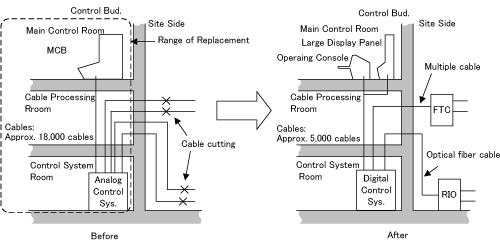
Fig. 2 Cabling Work
• Comprehensive combination testing
A successful completion of CBR within a limited length of time required minimizing the amount of on-site checking and verification activities and preventing incompatibilities and other problems that might arise on site. For this purpose, most of the upgrade equipment was subjected to comprehensive combination testing in a vendor's shop. The testing included performance and functional checking of each piece of the equipment, logic test, sequencing test, and loop test, thereby verifying all the circuit functions including operations from the main control board and display functions.
• Interface testing
The locally-installed FTCs and RIOs were installed in areas different from the area for the upgrade control boards. Thus, RIO interface testing was performed in parallel with the installation work of the new boards, using a control board for testing purpose having the same software functions as those of the new board. This resulted in reduced time required for restoration/ interface testing. (Fig. 3)
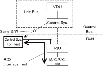
Fig. 3 RIO interface testing
The main control boards and associated equipment have been completely digitalized at Units 1 and 2 of the Ikata Power Station. This was the total digitalization of nuclear I & C systems at an existing plant, the first-of-its kind in the world. The project was carried out at both units during their refueling outages, which took place simultaneously for the first time in our company’s history. In a period of about four months, the CBR project was successfully completed in August, 2009, as scheduled. (Fig. 4)
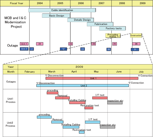
Fig. 4 CBR operation schedule
We strive for shortening the operation schedule further in upgrading construction of future large-scale electricity and I&C systems, referring to this construction plan and securing reliability.
- [1]"THE MAIN CONTROL BOARD UPGRADE PROJECT AT THE IKATA POWER STATION FOR UNITS 1 AND 2," Seventh American Nuclear Society International Topical Meeting on Nuclear Plant Instrumentation, Control and Human-Machine Interface Technologies NPIC&HMIT 2010, Las Vegas, Nevada, November 7-11, 2010.
- [2]"Modernization project of Ikata unit 1/2 main control room using full digital control board, " ICONE17 Proceedings of the17th International Conference on Nuclear Engineering, July 12-16, 2009.
- [3] "The Main Control Board Replacement Project for Ikata Units 1 and 2," Maintenology, Vol.8 No.4 (2010), pp. 19-24. (in Japanese)
Japan Society of Maintenology (ejam@jsm.or.jp)