


Classification
2 - A (Inspection Technology of Valve)
Nuclear power plants in Japan in general each have about 20,000 units of valves installed in them. Those valves had been mainly inspected based on time-based maintenance (TBM), where they are overhauled on prescribed time intervals. In January 2009, the Japanese government urged the nuclear power plants to streamline and optimize their maintenance activities. In line with it, a study is underway of the necessity to introduce in future a method considering condition–based maintenance (CBM), with which the timing and process of necessary repair is determined by measuring ongoing conditions of aging and damage.
Having predicted the growing importance in future of CBM, Okano Valve has successfully developed its own unprecedentedly innovative Ampere & Voltage Diagnostic System (AVD), to use in diagnosing motor-operated valves (MOV), which is expected to contribute to (a) enhancement of safety, (b) heightening of work efficiency and (c) improvement of working environment.
The AVD is a technology to diagnose a valve by measuring continuously the current and voltage of its motor at the Motor Control Center (MCC). Measured data are displayed as curves on the screen of the AVD apparatus. Those curves are interpreted to diagnose the ongoing performance of motor-operated valves. This innovative technology effectively precludes fieldworks such as valve remaking, use of strain gauges and installation of sensors which were indispensable in the conventional valve diagnostic method.
Being a condition monitoring and diagnostic system, where maintenance personnel are not required to come in contact with the valve under inspection, the system dismisses the possibility of erroneously damaging the valve while overhauling it. Especially, for nuclear power plants, the synergistic effect that radiation exposure of maintenance personal is reduced. The system requires no specific data transfer unit such as wireless, and also requires less number of sensors in data measurement, another advantage that simplifies working process, contributing to measurable reduction of working period of time, and minimization of personal error in measurement accuracy and of skill training of personnel.
Phase 2 : Industrial Confirmation Phase
- (1) Components: Moto-Operated Valve
- (2) Location: Motor, Gear Case and Valve
- (3) Others: Condition monitoring and diagnosis, on-line or off-line
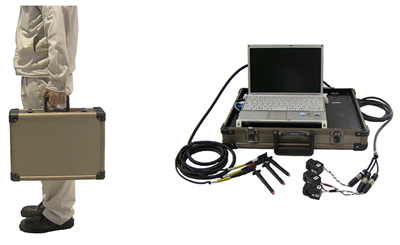
Fig.1 AVD Apparatus
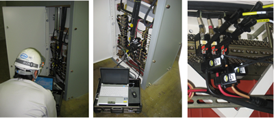
Fig.2 Measurement of Motor Current and Voltage at Motor Control Center
Fig.3 How to use AVD Apparatus
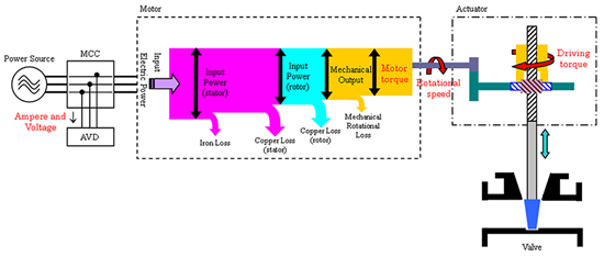
Fig.4 Model of Drive Force Transmission Mechanism of Motor-Operated Valve, and Layout of Measurement Process
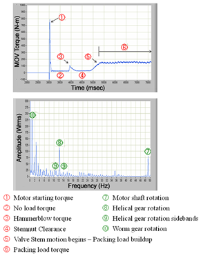
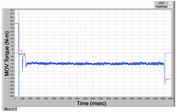
Fig.7 MOV torque vs. time after motor starts (AVD Validation Test Data)
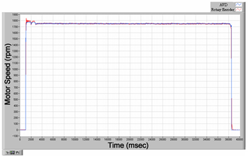
Fig.8 Motor speed vs. time after motor starts (AVD Validation Test Data)
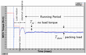
Fig.9 MOV torque curve after valve opening
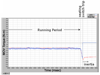
Fig.10 MOV torque curve before valve closing
Case 1: Packing Failure
The valve has a grand packing installed in it to have it produce sealing effect on its moving parts. As the grand packing deteriorates, the friction resistance between the ground packing and the valve stem grows bigger. Therefore, a motor-operated valve with its deteriorated grand packing needs its elevated driving torque, i.e. a larger torque value to keep it running. See Fig. 11.
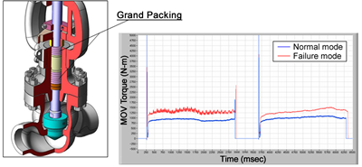
Fig. 11 Detection of Packing Failure
(MOV torque comparison between normal and failure modes)
Case 2: Unseating Torque
A motor-operated valve with its maladjusted stop position may have its seating torque exceeding its design value and cause the gate valve to have its seat cracking, or the vessel to have its internal pressure rising irregularly. It is possible to discover the incidence by monitoring the unseating torque that develops right after the valve starts its opening motion. See Fig. 12.
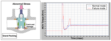
Fig. 12 Detection of Unseating Torque
(Unseating Torque comparison between normal and failure modes)
Case 3: Stem Nut Wear
The motor-operated valve has a part called "stem nut" installed in it. The role of the stem nut is to convert the revolving motion of its drive mechanism into the reciprocating motion that is transmitted to the valve stem. The stem nut has threads cut over its inner surface. The material of the stem nut is in general made of a copper alloy softer than the metal of the valve stem in order to prevent seizure between metallic threaded portions of both parts. As the lubricant coating deteriorates as time passes while the valve is in service, the stem nut has its threads worn out gradually. The more the threads wear out, the bigger becomes curve clearance right after the valve start-up. By monitoring this characteristic together with valve lift, the progressive wear of stem nut threads can be measured. See Fig. 13
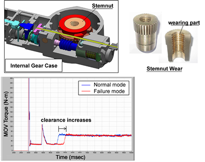
Fig. 13 Detection of stem nut wear
(MOV torque comparison between normal and failure modes)
Case4: Bearing Failure
Bearing failures not only in motor-operated valves but also in any other rotating drives lead to the waning reliability of the mechanical systems they are in. The AVD technology, which, analogous to general vibration analyses, can analyze the frequency of the waveform pulsation of the electric power that has been obtained by measuring electric current and voltage, is instrumental in detecting irregular motion of rotating parts including bearings. See Fig.14.
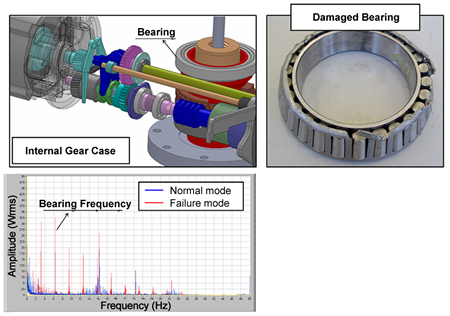
Fig.14 Detection of bearing failure
(Motor power spectral comparison between normal and failure modes)
Case5: Gear Failure
Motor-operated valves in general employ a speed reducer with gear mechanism for their drives. The purpose is to amplify motor torque by reducing motor’s rotating speed. The gear mechanism is however vulnerable to damage because of likely inadequate lubrication or improper installation. As in Case 4 above, irregularities of the gear mechanism can be detected by means of frequency analysis of electric power. See Fig.15.
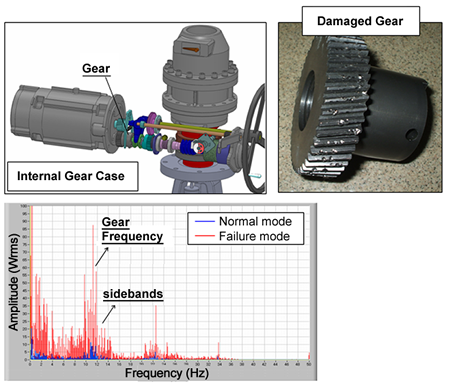
Fig.15 Detection of Gear Failure
(Motor power spectral comparison between normal and failure modes)
Tokyo Electric Power Company has so far collected and evaluated data on approximately 2,000 units of motor-operated valves installed at its Fukushima Dai-ichi, Dai-ni, and Kashiwazaki-Kariwa nuclear power plants. At the same time, the company has launched the compilation of a database for them. Also, it is underway of studying the quantification of the standards to manage the condition monitoring maintenance of its motor-operated valves.
- [1]K.Nagaiwa, K.Tanaka, K.Oyama, S.Hikita, A.Kawamoto, Conditon Based Maintenance of the Motor Operated Valve in Nuclear Power Plant, The Proc. of 7th Annual Conference of the Japan Society of Maintenology, Omaezaki, pp.510-514, July 2010. (in Japanese)
Japan Society of Maintenology (ejam@jsm.or.jp)