


| Vol.2 No.1 |
| General Articles |
| Vol.2, No.2, GA13 |
|
|
Shinro Hirano1, Kenichi Hamasaki1, and Koji Okimura2
1 Nuclear Power Division, the Kansai Electric Power co.,Inc 2 Kobe Shipyard & Machinery Works, Mitsubishi Heavy Industries, Ltd. |
1. IntroductionPWSCC (Primary Water Stress Corrosion Cracking) in Alloy 600 has been observed many times in actual plants. For preventing PWSCC, and also enhancing the reliability of components, various kinds of countermeasures have already been performed in Japan by utilities and Mitsubishi Heavy Industries since 2001. In this paper, various technologies to mitigate or prevent PWSCC and the related chronology of our research and development are introduced at first, and then some examples of our actual applications of these technologies are also described. The next two papers, on Steam Generator inlet nozzle issues and Reactor Vessel outlet nozzle issues, present major events of PWSCC problems which have happened recently in Japan, and countermeasures which have been applied to those problems. 2. Major events of PWSCC in the pastIn 1970s many cases of PWSCC were detected by ECT (eddy current testing) in Steam Generator tubes especially those made of the mill annealed Alloy 600 base material. Apart from Steam Generator tubes, the small leakage that occurred at one of the penetration nozzles of the Reactor Vessel closure head in Bugey-3 (France) in 1991, is well known as a major failure event of Alloy 600 base materials. In addition to failure experiences of base materials, failures also occurred in Alloy 600 weld material, such as in the Reactor Vessel outlet nozzle in VC Summer (US) in 2000. In Japan, no defect was found in Alloy 600 weld material until around 2000. However, in 2003 one of the Pressurizer nozzles in Tsuruga-2 had a small leak at the dissimilar weld joint. In 2007, at an inspection prior to mitigation, shallow defects of PWSCC have been confirmed at many Steam Generator inlet nozzles in many plants. In addition, one of the Reactor Vessel outlet nozzles in Ohi-3 showed a defect about 20mm in depth in the Alloy 600 portion of the weld. Figure 1 shows the major events of PWSCC in the past.  Figure 1 The Major Events of PWSCC in The Past 3. Locations of Alloy 600 in Japanese PWR plantsLocations of Alloy 600 in the PWR Primary Coolant System (RCS) are shown in Figure 2. Alloy 600 is generally used in dissimilar weld joints on the RCS boundary that connect the low alloy steel nozzle to the stainless steel piping. 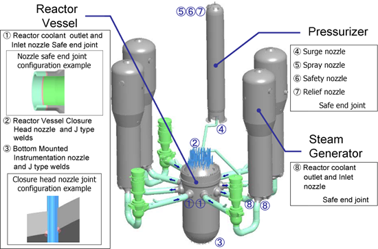 Figure 2 Locations of Alloy600 in PWR Reactor Primary Coolant System 4. Technologies against PWSCC and Chronology of research and developmentThree factors, sensitive material, severe environment and high tensile stress, all being present together will cause PWSCC. If any of these factors are removed, this will avoid serious damage from PWSCC. Various technologies have been developed to accomplish the removal or modification of each factor. (See Figure 3) 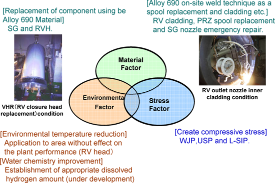 Figure 3 PWSCC Preventive Technologies 4.1 Efforts for Material ImprovementAlloy 690 shows far better PWSCC resistance than Alloy 600, because Alloy 690 contains double the amount of chromium (Cr) content than Alloy 600. Alloy 690 was first used for the Steam Generator tube at plant constructions in the late 1980’s. Subsequently Alloy 690 use has expanded to the tubes of Replacement Steam Generators, to the dissimilar weld joints in plants, and to the material of penetrations of the Replacement Vessel closure head. 4.2 Efforts for Environmental ImprovementIn order to reduce the PWSCC sensitivity of Alloy 600, design modification has been applied to the reactor internals in some plants, e.g., for slightly lowering the temperature around the vessel head penetrations. Moreover, an optimization of the dissolved hydrogen in RCS has been discussed recently from the stand point of improving primary water chemistry. 4.3 Effects for Stress ImprovementAfter the significant leakage event at Bugey-3 in 1991, some mitigation technologies have been developed that could reduce the tensile stress level effectively on the material surface. The chronology of developments for stress improvement technologies is shown in Figure 4. However, it can be difficult to apply some of these techniques at specific locations, so each mitigation approach has features that best match each application. For example, Water Jet Peening (WJP) can be applied underwater; Ultrasonic Shot Peening (USP) can be applied in dry conditions; and Laser irradiated Stress Improvement Process (L-SIP) can be applied to the outer surface when the access from inside is difficult. 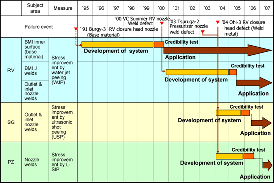 Figure 4 Chronology of Development for Stress Improvement Technologies 5. Stress Improvement Technologies5.1 Development of Surface Stress Improvement MethodThe principle of these techniques is to develop plastic strain and a compressive stress state in the surface layer of the sensitive material. This mitigates or eliminates the tensile stress factor that can lead to PWSCC. 5.1.1 Water Jet Peening (See Figure 5)When high-speed water jet is produced under water through a nozzle, a large amount of cavitation bubbles are produced in the water along the edge of the jet. Then those cavitation bubbles collapse, generating the shock pressure waves which cause plastic strain and a compressive stress on the material surface.
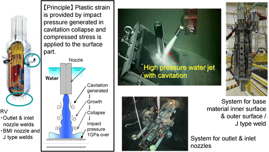 Figure 5 Water Jet Peening (WJP) for Reactor Vessel 5.1.2 Ultrasonic Shot Peening (See Figure 6)This process is similar to conventional shot peening except the shot material is somewhat larger and the shot is driven against the material to be peened by ultrasonic vibration transmitted from the piezo-elements. The shot striking the surface of the material cause plastic deformation and produces compressive stress in the material surface.
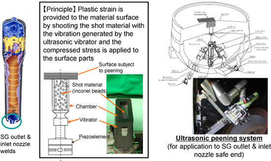 Figure 6 Ultrasonic Shot Peening (USP) for Steam Generator 5.1.3 Laser irradiated Stress Improvement Process (L-SIP) (See Figure 7)Outer surface of the structure is rapidly heated and temperature difference generated in the structure plate thickness leads to heat expansion strain and compressed stress environment.
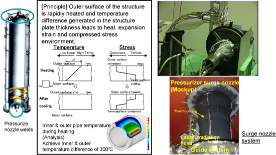 Figure 7 Outer Laser irradiated Stress Improvement Process 5.2 Verification of peening effect applied on an existing defectThe peening effect can modify the material surface stress condition from tensile to compression, but in general its effect would be confined closely adjacent to the surface. In order to ensure the compressive effect extends deep enough to prevent PWSCC, both WJP and USP had been verified that can generate compressive stress to the depth of 1mm. In addition, even when some shallow defects already exist on the material surface, WJP and USP have been confirmed to still be effective and that they do not have any harmful influence in the presence of existing defects. Figure 8 shows the after peening stress condition for each case, with or without existing defects. Residual stress was measured by the X-ray diffraction method. WJP and USP can provide compressive stress properly in both a region with no cracks and around a crack; the value of the residual stress shows little difference.
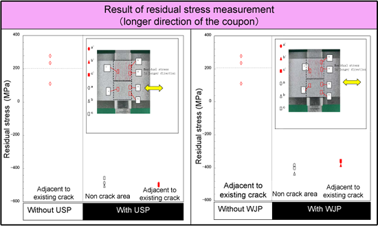 Figure 8 Effectiveness of Residual Stress Improvement The specimen was cut off along the central line of the 40-mm width, and WJP or USP was applied to only one of the cut pieces. Then, SCC testing was carried out in polythionic acid under the typical stress conditions encountered during operation (applied by means of four-point bending) to determine whether SCC develops after testing. SCC development was done by the destructive examination. A magnified observation was carried out on two cross sections for each test condition to measure the depth of all defects observed, and the result was graphed on a Weibull plot. The test results are shown in Figure 9 as a representative example. After peening, there was no significant difference in the defect depth between the specimens with and without SCC testing, suggesting there was no development of SCC. Hence, the WJP and USP methods are accepted by the Japanese regulatory agency.
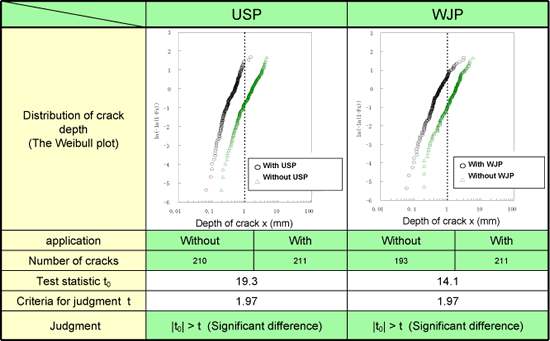 Figure 9 Effectiveness of Residual Stress Improvement 5.3 Development of Repair MethodBeginning around 2000, even though no PWSCC problem had been observed in dissimilar metal welds at that time in Japan, several repair methods were developed as a contingency plan, as well as for use a potential use as a preventive for these problems. Typical repair methods are shown below. 5.3.1 Defect Removal Method (See Figure 10 to Figure 11)
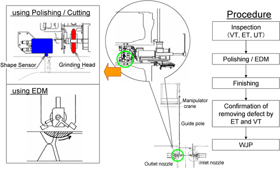 Figure 10 Repair Methods of Defect Removal
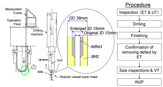 Figure 11 Repair Methods of Defect Removal 5.3.2 Spool Piece Replacement Method (See Figure 12)
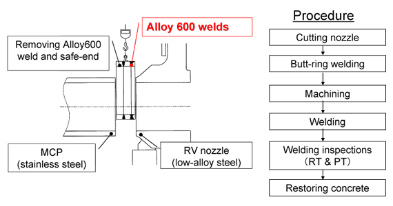 Figure 12 Repair Methods of Spool Piece Replacement 5.3.3 Installation of New Pressure Boundary (See Figure 13)
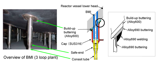 Figure 13 Repair Methods of installation of new boundary (Cap repair for BMI) 6. Field ExperienceAs a preventive maintenance, several stress improvement approaches, such as WJP, USP and L-SIP, have been applied to actual plants in Japan. In addition, when a leakage event occurred or some defects were found in an inspection, some contingency methods have applied and performed successfully. In the Kansai Electric Power, examples of field experiences are described as follows.
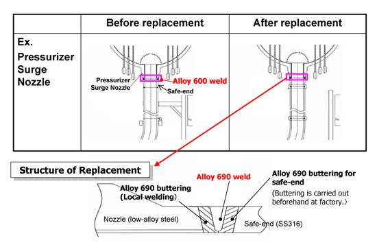 Figure 14 Pressurizer Nozzle Mitigation Method of Spool Piece Replacement |
|
Vol.10 No.2(Aug) |
|
| < Other Issues | |
|---|---|
 |
A New Mechanical Condition-based Maintenance Technology Using Instrumented Indentation Technique |
 |
Survey robots for Fukushima Daiichi Nuclear Power Plant |

Contacts
(EJAM): ejam@jsm.or.jp
(JSM): secretariat@jsm.or.jp
HP: http://www.jsm.or.jp
(in English)
![]()