


Tokyo Electric Power Co, Inc.
TOSHIBA Corporation
Hitachi-GE Nuclear Energy, Ltd.
Vol.2, No.3, NT28
Review on Conservatism of Guideline for Inspection and Evaluation to BWR internals
1. Technical summary
Classification
3 - B (Evaluation technology for SCC)
"Guideline for Inspection and Evaluation of Reactor Internals" (abbreviated as Guideline, hereafter) by Japan Nuclear Technology Institute (abbreviated as JANTI, hereafter) are published through the deliberation in "Study Group on Guideline". Published Guideline are usually taken into "Rules on Fitness-for-service (FSS code)" of Japan Society of Mechanical Engineers (JSME). FSS code is being endorsed by governmental regulator stage by stage. New maintenance technologies published as Guideline are authorized technically and it is possible to apply to actual nuclear plant if governmental regulator agrees individually.
As for Japanese BWR core shroud, when stress corrosion cracking (SCC) is found by inspection, continuation of the plant operation is decided by the result of integrity evaluation performed according to FSS code that has taken the evaluation procedure specified in Guideline for core shroud[1]. Fig.1 shows the summary concept of the evaluation procedure. When SCC is found, crack growth in future is evaluated by the procedure that Guideline specifies. The next essential inspection time is decided so that the expected remaining cross section is greater than the minimum required area to keep the structural integrity of core shroud. If the result of structural integrity evaluation shows that current remaining cross section is not enough, countermeasure such as repair or replacement is required before restart of plant operation.
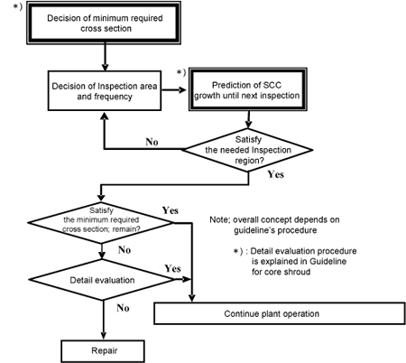
Fig. 1 Concept of inspection and evaluation of core shroud
2. Development phase
Phase 3: Publicly-accepted Phase
3. Scope
Scope of this article is consideration through the comparison of actual inspected core shroud SCC growth and growth predicted by the evaluation procedure specified by Guideline for core shroud. Japanese current available data are studied thanks to Japanese BWR utilities.
4. Features
Prediction of core shroud SCC growth by evaluation procedure of Guideline has actually enough conservatism.
As a result of the comparison of actual inspected core shroud SCC growth data and predicted growth by the evaluation procedure specified by Guideline for core shroud, it was confirmed that in every investigated case, predicted core shroud’s SCC growth is much greater than the actually inspected one.
Study Group on Guideline will continue this kind of investigation and will study appropriate modification on current method after validating enough reason as feedback.
5. Examples of Application
Fig. 2 shows a structure of core shroud and weld joint numbers. Following examples of application are described with these weld joint numbers.
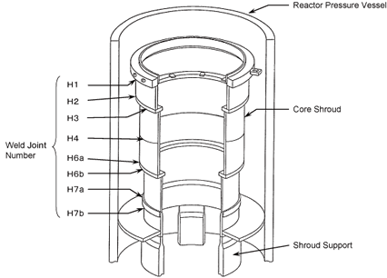
Fig. 2 Structure of core shroud
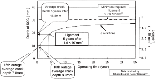
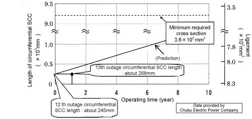
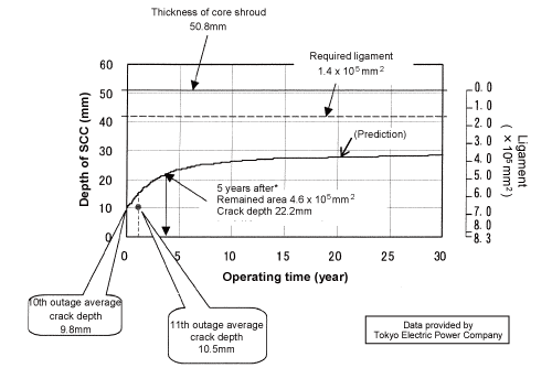
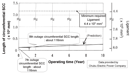
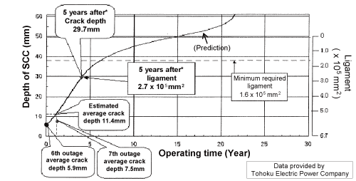
Fig.3, 4, 5, 6, and 7 show the comparison of actual inspected SCC growth result and predicted SCC growth evaluated before 1 cycle plant operation. There are 12 figures as result of investigation of all domestic applicable data. In every case we found that prediction by Guideline’s procedure gives greater growth than actual inspected growth.
Results of these investigation show that Guideline’s evaluation procedure can predict SCC growth conservatively enough. Application of Guideline procedure to core shroud is confirmed to be very effective to make rational operating plan for nuclear plant.
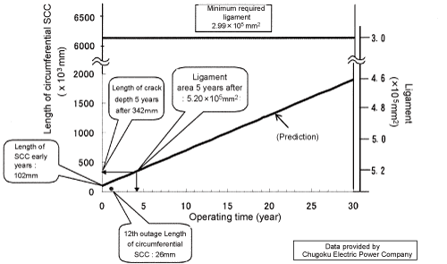
Onagawa unit 1 (out of H2 weld line)
Fig. 3 SCC growth of outer side of H2 weld (Ring region); prediction and actual inspection
 />
/>
Note) Length of circumferential SCC is defined actual inspected length + 2 × thickness of the sleeve (to increase conservatism)
Hamaoka unit 3 (inner of H4)
Note) Length of circumferential SCC is defined actual inspected length + 2 × thickness of the sleeve (to increase conservatism)
Shimane unit 2 (inner of H4)
Fig. 4 SCC growth of inner side of H4 weld; prediction and actual inspection
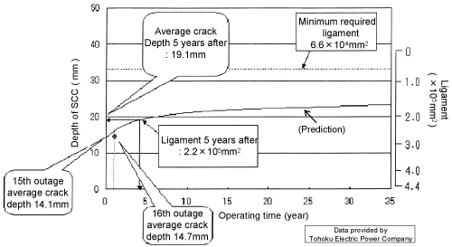
Onagawa unit 1 (outer side of H6a weld line)
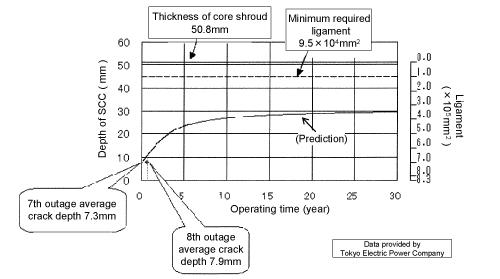
Kashiwazaki unit 3 (outer side of H6a weld line)
Fig. 5 (a) SCC growth of outer side of H6a weld; prediction and actual inspection
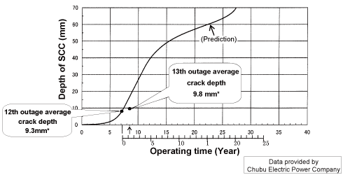
Note*) Averaged value of fixed examination area of 30° - 61°
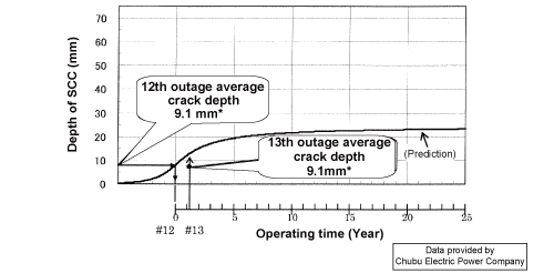
Hamaoka unit 3 (Outer side of H6a)
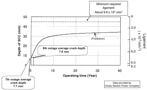
Hamaoka unit 4 (Outer side of H6a)
Fig.5 (b) SCC growth of outer side of H6a weld; prediction and actual inspection
Kashiwazaki unit 2 (Outer side of H6a)
Fig. 5 (c) SCC growth of outer side of H6a weld; prediction and actual inspection
Hamaoka unit 4 (inner side of H7)
Fig. 6 SCC growth of inner side of H7a weld (Shell); prediction and actual inspection
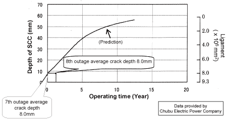
Onagawa unit 2 (inner side of H7)
Note *) Averaged value of fixed examination area of 297°- 332°
Hamaoka unit 3 (Inner side of H7)
Fig. 7 (a) SCC growth of inner side of H7a weld (Ring); prediction and actual inspection
Hamaoka unit 4 (inner side of H7)
Fig. 7 (b) SCC growth of inner side of H7a weld (Ring); prediction and actual inspection
6. Reference
- [1]Guideline for Inspection and Evaluation of reactor internals "Core Shroud" (4th revision), JANTI (in Japanese)
7. Contact
Japan Society of Maintenology (ejam@jsm.or.jp)