


The Kansai Electric Power Co. Inc.
Mitsubishi Heavy Industries, LTD.
Vol.3, No.3, NT40
Development of UT Sizing Technique of Cracks for Ni Alloy Welding
KEYWORDS:
Ni-alloy, DMW, SCC, Sizing, Phased-array
1. Technical summary
Classification
1 - B
In response to insufficient result of evaluation the depth of cracks by UT in the RV outlet nozzle weld at KEPCO Ohi unit 3, improvement study of accurate sizing techniques was carried out. The indication was found in the dissimilar metal welding which made by 600 series nickel base alloy and determined as stress corrosion crack (SCC) which were oriented to the axial direction of the nozzle. From subsequent investigations, it was estimated that shape of the crack was very long in the depth direction and narrow in the length direction as shown in Fig 1. Therefore in this improvement study, test piece with Ohi-type artificial SCC was prepared, and sizing performance of advanced method was evaluated. The sizing method used phased array techniques such as matrix phased array that had been in advance validated by an internal study of some manufacturer.
In the report of NT-24, the performance of advanced method was evaluated with SCC on plate test piece, but at this time, its performance was validated with the deep and narrow SCC given into a curving test piece simulating the actual nozzle weld and by the ultrasonic inspection (UT).
After the inspection test, the test pieces were cut to verify the true size of crack for the evaluation of sizing accuracy of each applied techniques. Additionally, another conventional method using surface echo from aperture plane was evaluated for backup method.
In sizing accuracy, root mean square error (RMSE) of the advanced method has been improved from 9.35 to 2.54 as compared with the conventional method. Moreover, using surface echo is considered to preliminary method and applying advanced method by reference to its result leads more accurate sizing effect.
Furthermore, it was confirmed that this advanced method is also effective to sample specimen of the actual plant.
2. Level of development/application
Phase 2 : Industrial Confirmation Phase
3. Scope
- (1) Components: Safe-end of Reactor Vessel
- (2) Location: Dissimilar Metal Weld of Safe-end
- (3) Material: 600 series nickel base alloy
- (4) Condition: Applicable in not only air but also immersion at room temperaturer
4. Features
- (1)SCC Test Pieces
In this study, 2 types of test pieces were made. The first type test pieces had deep and narrow cracks seen in RV outlet nozzle weld at Ohi unit 3, and other test peaces had a common shape cracks without any condition about depth and width. A total of 17 test peaces were made. After ultrasonic inspection was conducted with each techniques, all test pieces was cut and evaluated size and shape of cracks. Figure 1 shows the representative result.
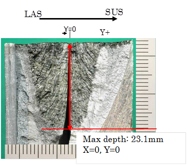
Fig. 1 Example of SCC fracture surface
- (2) Depth sizing method
As shown in figure 2, the inspection probe scanned inner surface of the nozzle. To evaluate depth of the cracks, phased array technique was applied as improved method. Large type matrix phased array UT probe was applied for the deep crack. This probe can be 3-Dimensional beam scan. And small type TRL phased array probe was applied for shallow crack. This probe is applied to a large angle of refraction. (Please refer the report of NT-24 to see the feature of these two probes.) And for comparison, 2 types of conventional probes with different refraction angle used at actual plant inspection were applied. Figure 3 shows UT probes used for this study. And figure 4 shows equipment for inspection of a nozzle.
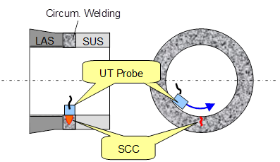
Fig. 2 Image of Inspection
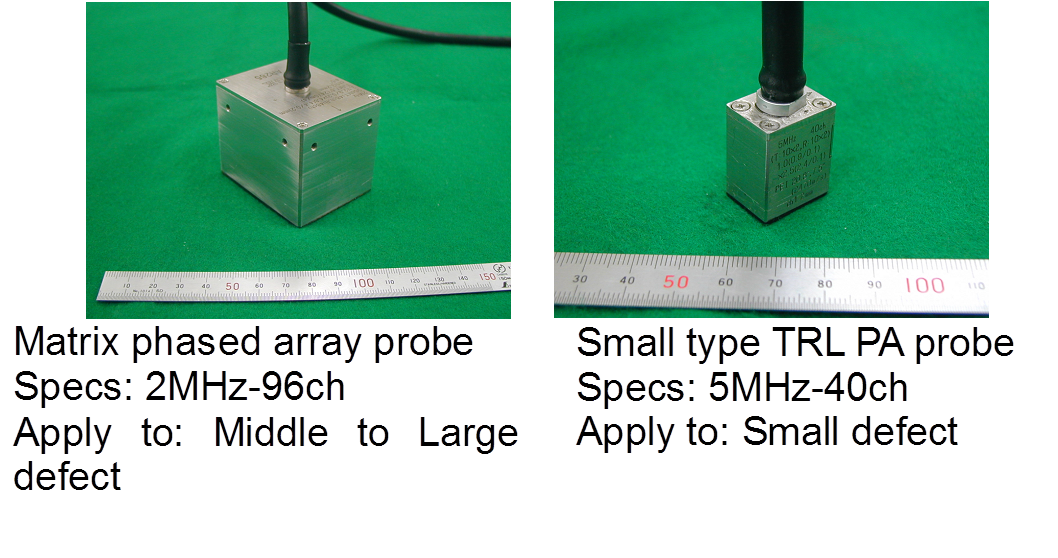
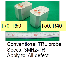
Fig. 3 Applied UT probes
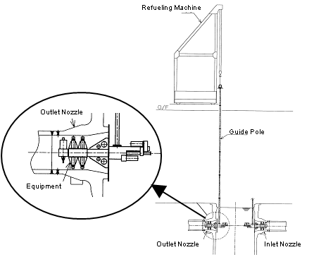
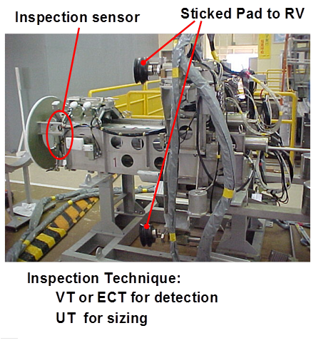
Fig. 4 Equipment for inspection of nozzle
- (3) Defect sizing accuracy
According to the study, the conventional method showed a good sizing performance at less than 15mm depth of crack, but it became extremely bad around 20mm depth of crack as shown in figure 5(a). On the other hand, the advanced method using phased array UT technique showed a relatively accurate sizing result around 40mm depth as shown in figure 5(b). Especially, by using a different probe suitable for each depth level, RMSE of the advanced method had been improved greatly to 2.54 from 9.35. Also, according to the result of the previous research, RMSE of conventional method was 7.9 and RMSE of advanced method was 0.92. It is estimated that these poor values of both RMSEs are because of a change from the planar test piece to the curving one and buttering and welding equivalent to those of the actual nozzle weld. Additionally, the tip echo used by the conventional method cannot be detected in some case, especially at in the deep crack area. In this case the sizing accuracy was determined with surface echo. Use of the surface echo is discussed below.
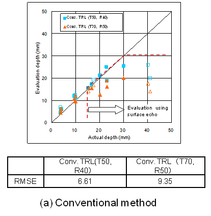
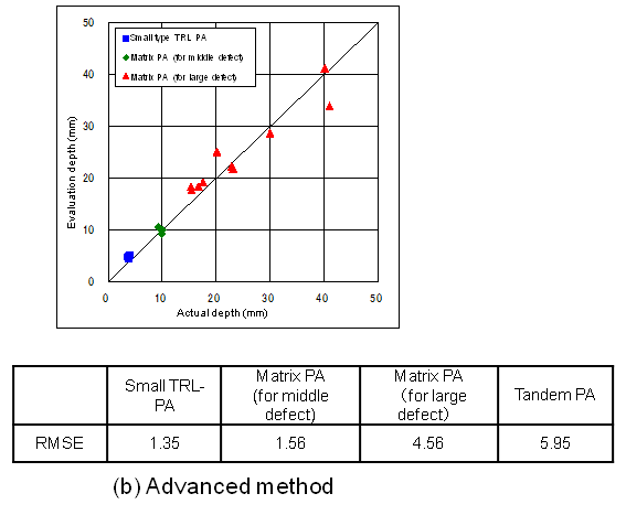
Fig. 5 Sizing accuracy of SCC
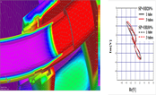
- (4) Detection performance for tip echo
Figure 6 shows detection ability of tip echo. In the shallow inspection area, small type TRL-PA and middle size defection probe of matrix PA showed better SN ratio of tip echo compared to conventional method and sizing accuracy was improved. On the other hand, in the deep inspection area, advanced method showed little difference from conventional method but tip echo was not detected using conventional method. In contrast, advanced method detected the tip echo with enough SN ratios and it made possible defect sizing.
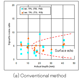
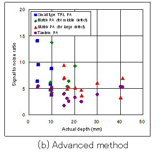
Fig. 6 Signal to noise ratio of tip echo
- (5) Use of defect surface echo
Even if tip echo was not detected with the conventional method, it was possible to estimate the size of defect by distribution of surface echo reflected from surface of the defect. Figure 7 shows the result of the sizing by the surface echo method. Especially, evaluation with setting threshold value as DAC 20% gave relatively good sizing accuracy. However, in the inspection area of over 15mm depth, surface echo itself couldn’t be detected by conventional method. So it was effective to evaluate by DAC 20% within 15mm depth area. From this result, sizing method using surface echo with DAC 20% has advantage within 15mm depth area, but it could lead to underestimation over 15mm depth area. So, using surface echo is considered to preliminary method and applying advanced method by reference to its result leads more accurate sizing effect.
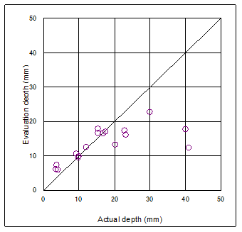
Fig. 7 Sizing properties using defect surface echo
(Conventional method, Threshold: DAC20%)
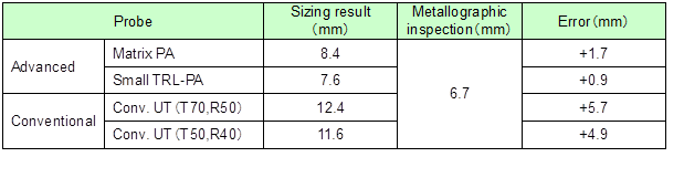
- (6) Investigation of sample curved out from actual equipment
In the preventive maintenance procedure at Tomari unit 1, a crack indication was detected at the replaced actual SG inlet nozzle. So, UT sizing method (conventional method and advanced method) was applied to inspection to research the property of crack and accumulate the inspection results. From the results of surface observation, enlarged observation of fracture surface and enlarged observation of cross-section surface the crack was estimated to PWSCC just like another crack of SG nozzle. And the depth was confirmed to 6.7mm. Table 1 shows the result of UT sizing. Even in this situation, the advanced method made better performance than the conventional method and especially optimally selected small type TRL-PA achieved best performance.
Table 1 Sizing evaluation results for actual plant sample
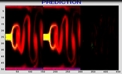
- (7) Example of inspection wave form
Figure 8 (video) shows the difference of conventional method and advanced method. From this video, it was find advanced method to be a very effective of deep area inspection.

Fig. 8 Difference of defect signal between conventional method and advanced method
5. Examples of Application
Applied to a domestic plant
6. Reference
- [1]J. NISHIDA, S. KAWANAMI, M. IDEO, T. MATSUURA, N. CHIGUSA, S. HIRANO, T. SERA, Development of the advanced phased array UT technique for accurate sizing of cracks in the nozzle welding, Preprints of 7th Annual Conference of the Japan Society of Maintenology, Omaezaki, pp.67-70, July 2010. (in Japanese)
- [2]NT-24 Development of the advanced phased array UT technique for accurate sizing of cracks in the nozzle welding
7. Contact
Japan Society of Maintenology (ejam@jsm.or.jp)