


| Vol.3 No.1 |
||||||||||||||||
| General Articles | ||||||||||||||||
| Vol.3, No.2, GA17 | ||||||||||||||||
A test facility employing a magnetic bearing for mechanical element tests |
||||||||||||||||
|
MASATO EGUCHI,1KIKUO NISHIYAMA2,KENICHI SUGIYAMA3
1Technology Development Department
Fluid Machinery Development Division
EBARA CORPORATION Fluid Machinery & Systems Company
2.3 Nuclear Pump Design Department EBARA CORPORATION Fluid Machinery & Systems Company |
||||||||||||||||
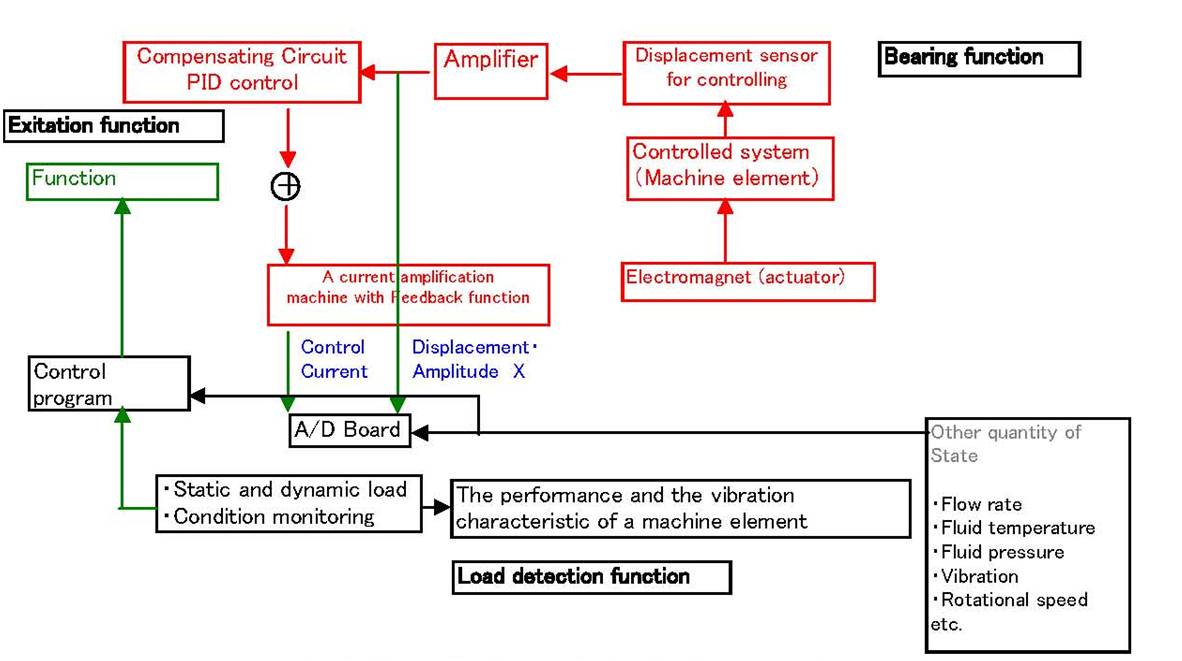
1. IntroductionIndustrial machines such as multistage centrifugal pumps including boiler feed water pumps and pumps for circulating cooling water play an important role in electric utilities and chemical plants. Such machines are used, for example, in nuclear and thermal power plants, as well as in oil refineries. The reliability of such machines is paramount since a failure can shut down operations causing monetary loss.The principal contributor to pump failure is uncontrolled vibration leading to breakdown of critical machine elements. Such vibration resulting from fluid discharge is characteristically due to the high viscosity and density of the operation fluid. The underlying science which enables the prediction and helps avoidance of this type of vibration is an important subject. Additional complications arise as the designer attempts to improve efficiency to obtain energy savings. Such improvements often require, for optimal operation of the pump, increases in the range of flow control. This, in turn, requires increases in the range of rotational speed and/or valve opening. The pump designer is required to provide a trouble-free design, and must guarantee the performance of the pump over the extensive operation range. The annular pressure seal, which serves to prevent leakage of the fluid being pumped, has an impact on the vibration characteristics, and has to be chosen carefully. The desire to obtain a good seal has to be balanced with the desire to reduce shaft vibration since the pressure seal characteristics necessary for meeting these requirements run counter to each other. The most serious vibration problems often arise when cavitation occurs at low flow rates. It is important to conduct an experimental simulation in order to identify the cause of vibration and initiate countermeasures. Our company has developed an apparatus for testing elements of a pump (impeller, annular pressure seal, bearing, mechanical seal, etc.) under large static and dynamic loads. The system can evaluate the performance of the machine elements with sufficient accuracy. We employ a magnetic bearing to realize the testing performance at an appropriately high level (shorter test time, lower cost and good measurement accuracy). Reasons underlying the use of a magnetic bearing include: (1) The non-contact state between the rotor and casing can be preserved. (2) The direct excitation of rotating shaft is possible by magnetic bearings. Moreover, it is easy to control amplitude, phase, and the excitation frequency accurately. Displacement and shaft excitation along 5-axes including radial and axial direction can be controlled independently. (3) A magnetic bearing can serve as a load detector. Accordingly, this apparatus can evaluate the static and dynamic load acting on the bearing directly. 2. Introduction of the machine element testing equipment2.1The outline and specification of testing equipmentOur company has two systems with different capacities for the examination of various machine elements. These facilities, developed and manufactured using in-house technology, employ an appropriate magnetic bearing unit with independent control along all axes in both radial and axial directions except in the rotational direction as shown in Fig. 1. (figure shows the medium sized test equipment)
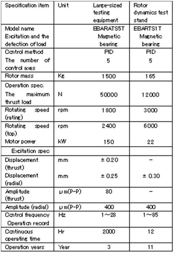
As shown in Table 1, the performance of magnetic bearing and the power of electric motor depends on the capacity (size) of the test apparatus. The performance and capacity was chosen according to the size and capacity of the machine element under test. The test procedure was also tailored appropriately.
Table.1 Specification for the Machine Element Testing Equipment
Fig.1 The Sectional drawing for machine element test equipment
The test equipment for medium-sized machine element was developed in 1999. The equipment is designed for evaluating the quality, dynamic properties and the noise characteristics of the non-contact annular pressure seal installed in an industrial pump[1]. The test stand was subsequently modified (in 2002 and 2004)to be able to measure the vibration characteristics of centrifugal impellers in relation to the change of flow rate or cavitation number. Additional modifications to the system was made to be able to: 1. Determine and evaluate inducer performance and dynamics for achieving both high suction performance and low vibration (in 2004 and 2006) 2. Assist the development of hydrostatic bearings (2009). The facility could perform endurance tests for submerged bearings with a surface temperature higher than 200ºC under boundary lubrication and overload condition (2010).
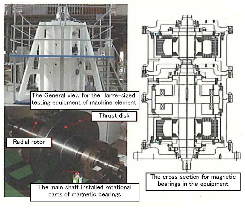
Fig.2 The Outline for the large-scale test facility
The large-scale test equipment was developed in 2008 for the purpose of improving the product and execute reliability verification tests of the mechanical seal. The basic structure of large-scale testing equipment for evaluating machine elements is similar to that of the medium-scale test apparatus.The apparatus adopted suitable user-assistance tools, such as sequence control and IT technology and reflects the technical know-how obtained through various examinations. The thrust magnetic bearing can support more than 5 tons and it’ s ability is outstanding despite the fact that the magnetic bearings have a radial air gap that exceeds l mm necessary to accommodate the excitation test of a long shaking stroke.
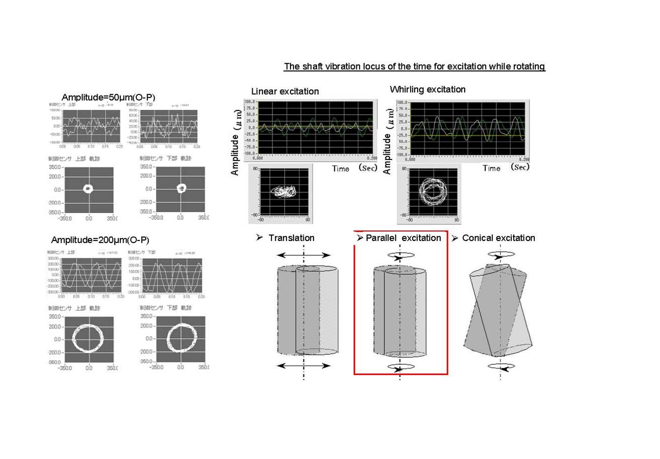
These various improvements permit a variety of test procedures including vibration characteristic measurements and reliability confidence tests under high fluid pressure and high temperature environment. The system offers fully unmanned operations, incorporating a cooling water supply system, an inverter, the high safe maintenance capability over a bearing controller, and automatic alarm in the event of an abnormal outbreak, etc. It is possible to test the equipment non-stop over a period exceeding 2000 hours, As seen from the specification of Table 1, these facilities allow tests under high thrust load conditions and in high-pressure environments. Moreover, it was designed to accommodate large stroke displacement and amplitude so that unusual vibration can be initiated also in the radial direction. As a result, the general performance and the vibration characteristic of a machine element can be measured under realistic operating conditions. 2.2 Functions of the testing equipments
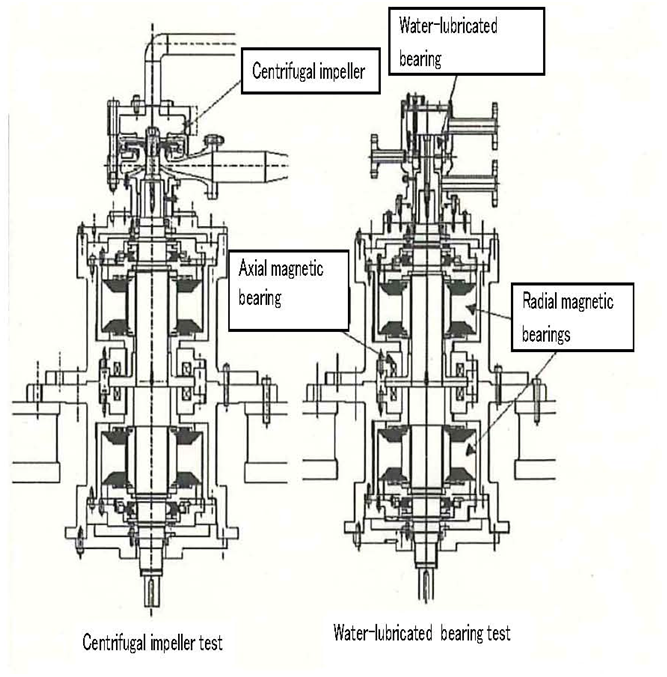
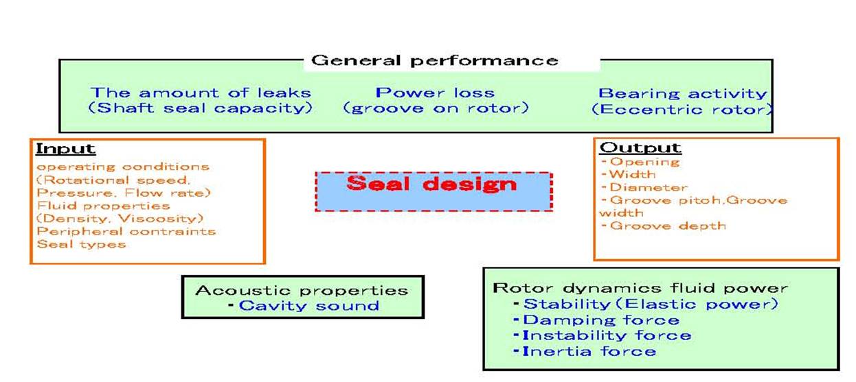
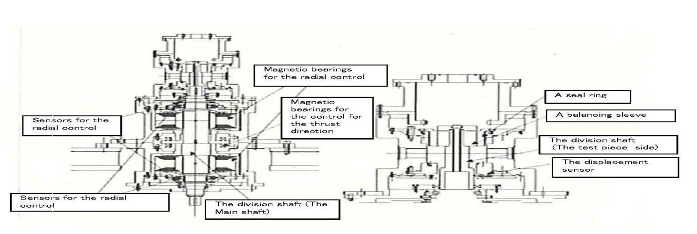
3. Examples of tests conducted by the machine element test standsAs described above, the test stands support a variety of tests for machine elements. Two typical test examples are introduced below.3.1 Performance evaluation test for non-contact annular sealsA non-contact annular seal is a machine element that significantly affects the vibration characteristics of a pump’s rotating shaft system. For pumps with low specific speed (NS), better shaft sealing performance improves the pump efficiency. However, the shaft sealing performance is inversely related to the vibration characteristics, and the evaluation of both parameters is required for practical applications. Therefore, the test stands evaluate the performance of non-contact annular seals based on the parameters regarding general performance, vibration performance, and acoustic characteristics (only for grooved seals), as shown in Figure 5 [2]. Figure 6 shows a cross-sectional view of each test stand under seal test conditions.
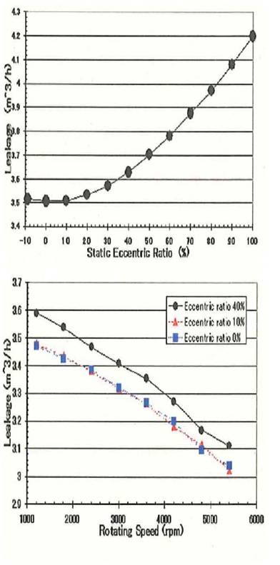
The most important function of non-contact annular seals is to reduce leakage from the high pressure side. We evaluate the shaft sealing performance based mainly on changes in shaft eccentricity, pressure difference, and rotating speed. Generally, more shaft eccentricity or greater pressure difference results in increased leakage, while higher rotating speed leads to decreased leakage. Figure 7 shows the leakage rate in relation to the eccentric ratio and the rotating speed. For this seal, the leakage rate is 20% higher at an eccentric ratio of 100% (the shaft is completely eccentric with no clearance left) than at an eccentric ratio of 0% (the shaft is at the center of the seal). This difference in shaft sealing capability together with changing eccentricity can be reduced by improving the shape of the seal. Thus, the test stands serve the purpose of contributing to seal design techniques for improving pump efficiency.
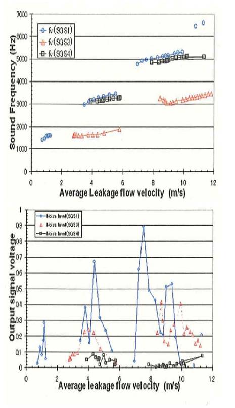
Grooved seals occasionally cause cavitation problems in practical applications. The test stands also help to solve the acoustic problem by conducting reproduction tests and reducing the noise level through the adjustment of the seal shape, as shown in Figure 8.
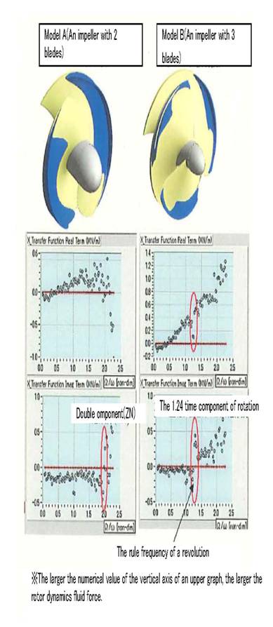
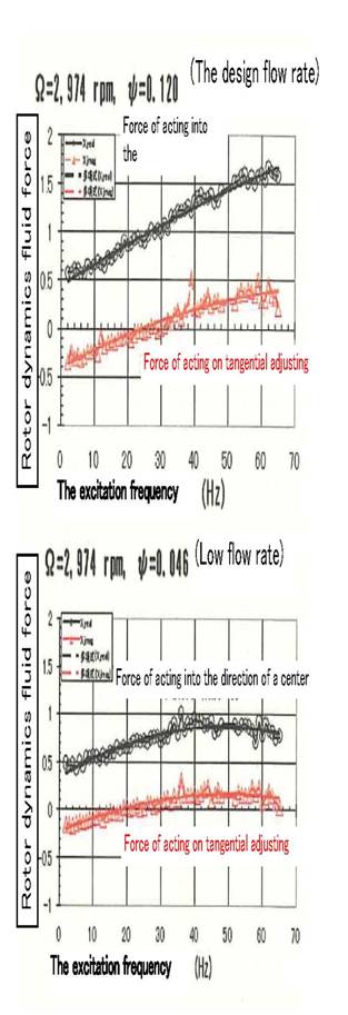
3.2 Impeller excitation testFor centrifugal impellers and inducers in volute or diffuser pumps, our focus is on the suppression of fluid instability as well as the improvement of techniques for clarifying and predicting the unstable vibration of the rotating shaft. Especially in inducers, piping vibration caused by cavitation surge or shaft vibration caused by rotating cavitation is associated with suction performance. The test stands are used to evaluate the inducer suction performance and the likelihood of the occurrence of abnormal vibration, so that optimal product components are developed with consideration given to hydraulic performance and vibration characteristics. As shown in Figure 9, the two-blade model A [3] provides excellent fluid dynamics at the blade passing frequency (ZN) under low NPSH conditions, exhibiting no specific resonance curve that may lead to abnormal vibration. For the three-blade model B [4], vibration frequencies specific to rotating cavitation are detected under low NPSH conditions, as is evident from the right graph in Figure 9; this model may produce abnormal vibration at lower NPSH values. For inducers to be developed, vibration evaluation tests are also performed through the quantification of steady fluid dynamics to examine their feasibility for products.
4. Conclusions
Our machine element test stands use magnetic bearings to control the position and vibration of the rotating shaft in a reproducible manner, which cannot be easily achieved with conventional test stands. Taking advantage of this feature, they facilitate product improvements through the effective use of measurement data obtained from various machine elements that make up pumps. They also allow the analysis of shaft vibration taking into account of the influence of flow, which is useful in estimating reliability and stability more accurately for practical applications. Thus, they can evaluate the vibration characteristics of products during the design phase. In addition to non-contact annular seals, the test stands support considerably rigorous tests, such as the measurement of pump impellers’ general performance and vibration performance and continuous endurance testing (destructive testing) for submerged bearings and mechanical seals, without problems. It has been demonstrated that the test stands can be applied to a wide range of applications. They aim to improve the performance of machine elements in broader application areas.
References
|
|
Vol.10 No.2(Aug) |
|
| < Other Issues | |
|---|---|
 |
A New Mechanical Condition-based Maintenance Technology Using Instrumented Indentation Technique |
 |
Survey robots for Fukushima Daiichi Nuclear Power Plant |

Contacts
(EJAM): ejam@jsm.or.jp
(JSM): secretariat@jsm.or.jp
HP: http://www.jsm.or.jp
(in English)
![]()