


The Kansai Electric Power Co., Inc.
Mitsubishi Electric Co.
Vol.3, No.2, NT36
Transformer Condition Monitoring Diagnostic Technologies to Detect Deterioration and Faults
KEYWORDS:
transformer, diagnostic technologies to detect deterioration, diagnostic technologies to detect faults
1. Technical summary
Classification
Classification ③-Electric and instrumentation equipment ③-Diagnostic technology
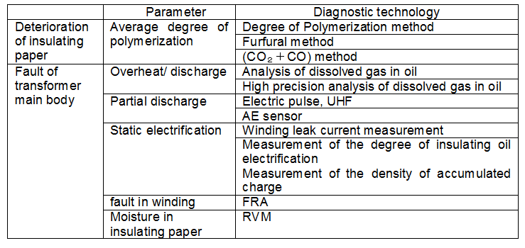
Each nuclear power plant uses various types of transformers. Condition monitoring technologies applicable to transformers are essential to assure stable plant operation. The major condition monitoring technologies used for the diagnosis of transformer conditions are shown in Table 1.
Among these, this paper addresses a diagnostic technology to detect insulating paper deterioration and another one to analyze dissolved gas in oil because both of these technologies are essential in determining the operability of a transformer through planned maintenance programs and detection of deterioration.
Table. 1 Diagnostic technologies applicable to transformers
(1) Diagnostic technologies to detect deterioration of insulating paper1),2)
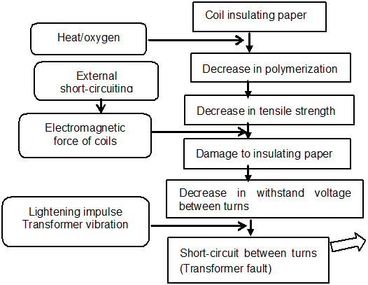
A decrease in the average degree of polymerization (i.e., a decrease in tensile strength) of coil insulating paper of a transformer, which is caused by thermal deterioration occurring with operating years, is supposed to be one of the main factors which determine the average service life of a transformer. Figure 1 shows the flow of a transformer fault due to deterioration of coil insulating paper.
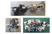
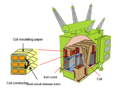
The coil insulating paper plays an important role as an insulator between coil conductors. Figure 2 shows the internal structure of a shell-type transformer, including the location of insulating paper.
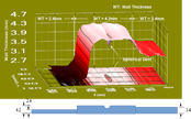
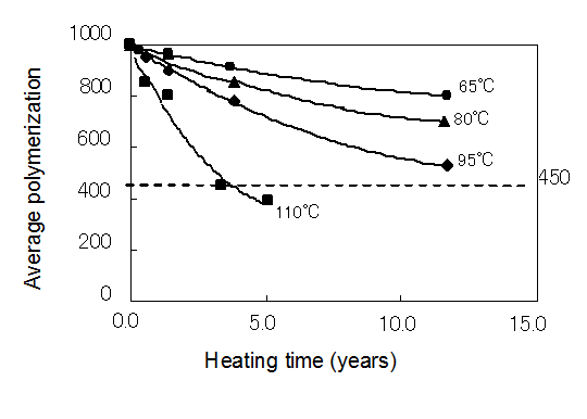
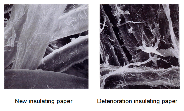
Figure 3 shows the relationship between the average degree of polymerization, temperature and heating time. Figure 4 shows pictures taken by the electronic microscope.
The service life of a transformer can be estimated by calculating the time when the average degree of polymerization of the insulating paper on the hot spot coil area reaches the end of service life using a regression equation, which was obtained by the deterioration characteristics shown in Figure 3, considering operating data.
The average degree of polymerization can be determined by sampling insulators (press boards) from the concerned transformer, or estimated based on the amount of furfural in oil, which is a decomposed product of insulating paper, and the amount of CO2+CO.
Insulating paper has a polymeric molecular structure consisting of cyclic hexagonal glucose rings. The number of glucose ring cycles is called the average degree of polymerization. An average degree of polymerization at 450 is considered to be the life time of insulating paper.
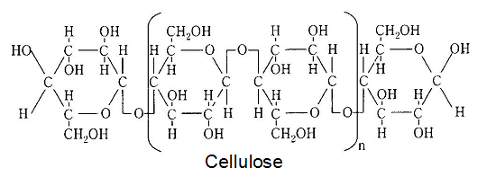
Fig. 5 Molecular constitution of cellulose
(2) Diagnosis of possible faults in the transformer main body
a. Dissolved gas analysis method
The analysis of dissolved gas in oil is widely utilized to determine the existence of faults, characterize faults, if any, and determine the degree of a fault inside a transformer by analyzing gases generated from the decomposition of insulating oil due to partial discharge or overheat, and measuring the amount of CO2 and CO resulting from damage to the solid insulation nearby.
An on-line gas analysis system has been developed for the early detection of faults and streamlined maintenance. This system is able to automatically and periodically analyze the 6 chemical ingredients* of combustible gas, which is required for the diagnosis of transformer condition.
Figure 6 shows the on-line dissolved gas analysis system, which is installed adjacent to a transformer.
*6 chemical ingredients:H2,CH4,C2H6,C2H4,C2H2, and CO
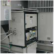
Fig. 6 On-line dissolved gas analysis system
b. Advanced dissolved gas analysis method3)
An advanced method of analyzing dissolved gas has been recently developed.
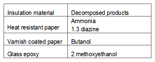
The advanced analysis method is able to determine the defective locations (insulating materials), which conventional analytical techniques were not able to discriminate, by comparing decomposed products specific to each insulation material and those detected in the concerned transformer.
Heating tests were conducted on the 11 types of insulation material, which are used inside a transformer. It was revealed that the heat resistant paper, varnish coated paper and glass epoxy generated decomposed products specific to each material as shown in Table 2.
The advanced dissolved gas analysis method may fail to detect some decomposed products resulting from the aging process. With less data accumulated through the application of this new technique to actual plants, any target value for decomposed products has been set yet. It is planned to set the target value for each decomposed product in future.
The decomposed products specific to each insulation material are not likely to be easily gasified because of its high molecular weight and high boiling point. In addition, measurement to ppb order is required for the analysis. To meet these conditions, gas chromatography-mass spectroscopy (GCMS) is used to analyze qualitatively and quantitatively the ingredients extracted by the cold concentration technique as shown in Figure 7. Figure 8 shows the advanced gas analysis system.
The introduction the advanced diagnostic technologies mentioned above to operating plants has contributed to improving and maintaining stable plant operation.
Table. 2 Decomposed products specific to each insulation material
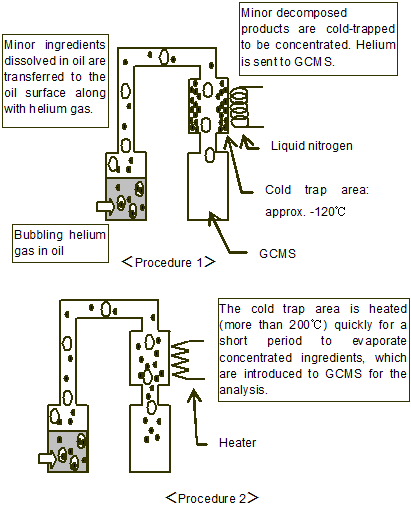
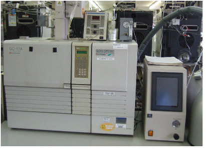
ingredients dissolved in oil (Cold trap method) Fig.8 Advanced gas analysis system
2. Development phase
This technology is defined as the Stage 3.
3. Scope
This diagnostic technology is applicable to all oil-immersed transformers.
4. Features
(1) Diagnostic technology to detect deterioration of insulating paper
This technology is intended for the diagnosis of deterioration in individual transformers considering the characteristics and operating conditions of each transformer. Prediction of the service life of insulating paper, which is a key component of a transformer, enables systematic planning of maintenance, including replacement, and thus prevents accidents from occurring.
(2) Dissolved gas analysis method
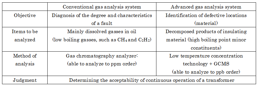
Table 3 shows a comparison between the conventional gas analysis system and advanced gas analysis system.
The conventional gas analysis system is used mainly for the diagnosis of the degree and characteristics of deterioration, such as overheat and electric discharge, occurring inside a transformer. On the other hand, the advanced gas analysis system is aimed at determining the defective material, and thus identifying the location of deterioration. The conventional and advanced gas analysis systems can compensate for with each other to enhance the accuracy of determining if continued operation of the concerned transformer is acceptable or not.
While the conventional gas analysis system performs routine analyses once or twice a year, the on-line gas analysis system is able to perform automatic analyses at given intervals, which can contribute to early detection of a fault.
Table.3 Characteristics of conventional and advanced gas analysis systems
5. Examples of Application
(1) Diagnostic technology to detect deterioration of insulating paper
The diagnostic technology to detect deterioration of insulating paper was applied to the transformers used at Kansai Electrics Mihama, Takahama and Ohi nuclear power stations. Considering the results, the main transformers of Mihama-1, Takahama-1 and Ohi-1 were replaced with new ones.
(2) Dissolved gas analysis method
In some cases, a combined use of conventional oil analysis system and advanced dissolved gas analysis technology successfully discriminated the faults in the oil pumps and transformers, which have different insulating material.
The on-line gas analysis system, which enables automatic analysis at given intervals, is installed adjacent to major transformers, including main transformers, to perform diagnostic monitoring for fault detection.
6. Reference
- [1]“Maintenance management of oil-immersed transformers”, Electric Technology Research Association, No.5 (Part 1), Vol. 54, February 1999
- [2]“Diagnostic and replacement technologies for electric equipment”, Technical Report of the Institute of Electrical Engineers of Japan, No.831, July 2001
- [3]“Guideline for the refurbishment of electric power transformers”, Electric Technology Research Association, No.1, Vol. 65, September 2009
7. Contact
Japan Society of maintenology (ejam@jsm.or.jp)