


Classification
1 - C
Periodical measurement of pipe wall thinning for nuclear power plant is performed manually and it is performed based on JSME code which is Japanese rules on pipe wall thinning management. However, there are following concerns.
-
Measured values may vary depending on the stability of measurement position and condition of contact.
-
The additional work for installation and removal of heat insulating material and a scaffold is required at every measurement.
-
The stable measurement is difficult on complex geometry, such as T-jointing of small pipe, because of the curvature.
-
The continuous wall thinning monitoring in plant operating is impossible because of high-temperature.
Therefore, we developed the thin-film UT sensor for high-temperature use. Since the thickness of the sensor is thin (less than 1.0mm), it can be installed under the heat insulator of pipe. And its flexibility enables to measure the thickness on complex shape, such as T-jointing of small pipe. Moreover, it has the high-temperature durability and it can be continuously attached during plant operation.
We performed verification tests of measurement accuracy and load test of heat and irradiation durability. Furthermore, field trial was performed at actual nuclear power plant.
In this paper, we introduce features of the thin-film UT sensor, results of the verification tests and field trial.
- (1) Components: Piping and Vessels
- (2) Location:
Base materials of Piping and Vessels
- (3) Materials: Carbon steel, Law alloy steel
- (4) Condition: In the air (from room temperature to 200ºC)
(1)Summary of thin-film UT sensor and measurement system
The thin-film UT sensor is shown in Fig.1. The thin-film UT sensor consists of top electrode, piezoceramic film and bottom electrode. Since the thickness of the sensor is less than 1.0mm and it is flexible, it can be installed under the heat insulator of pipe. It is also possible to measure complex shape, such as T-jointing of small pipe. Moreover, it has the high-temperature durability and it is applicable to the location of the maximum temperature 200 degrees C or higher by selecting material of piezoceramic film. There is no sensor in current market which has high temperature durability, very thin body which can be set under the heat insulator, and flexibility which can be attached to complex geometry.
The measurement configuration using the thin-film UT sensor is shown in Fig.2. The thin-film UT sensor is fixed using adhesive material under heat insulator. Each sensor is connected to the relay box placed outside of heat insulator in order to bundle signal wires. In case of periodical wall thinning measurement, portable measurement equipment is connected to the relay box. Therefore, it is possible to measure wall thickness without removing heat insulator. Moreover, in case of wall thinning monitoring, data acquisition station is connected to the relay box and collects the wall thickness data continuously with appropriate interval. Thus, because of the thin-film UT sensor enables acquiring the UT data without tester’s operating, there is no measurement error by tester’s pressing force and sensor position every measurement. Therefore, thin-film UT sensor enables acquiring the reproducibility and objective thickness data.
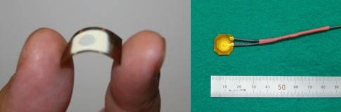
Fig.1 Thin-film UT sensor
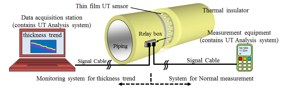
Fig.2 Measurement system
(2) Verification test
i) Measurement accuracy of thickness
In order to confirm measurement accuracy of thin-film UT sensor, thickness is continuously measured on plate which is ground by 10μm unit using milling machine as shown in Fig.3. As shown in Fig.4, root mean square error between grinding value and measurement value was less than 2.3μm on the plate of approximately 10mm of thickness. Therefore, it is considered that thin-film UT sensor has enough accuracy to perform periodical measurement of pipe wall thinning.
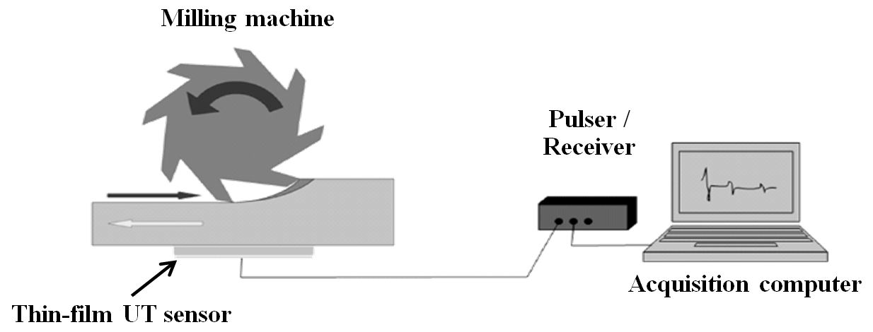
Fig.3 Measurement configuration on plate
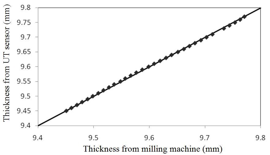
Fig.4 Measurement accuracy on plate
Moreover, in order to confirm measurement accuracy of thin-film UT sensor on complex shape, we measured wall thickness of T-joint piping and elbow piping by using both thin-film UT sensor and small size UT sensor as shown in Fig.5 and Fig.6. The specification of mockup is shown in Table1.
As shown in Fig.7, maximum difference between both sensors was less than 0.1mm and it is considered that thin-film UT sensor has same measurement accuracy as small size UT sensor. On the other hand, although the stable measurement using small size UT sensor had a difficulty because of point contact. Thin-film UT sensor had an advantage of stable measurement because it could fit the surface of complex geometry because of its flexibility.
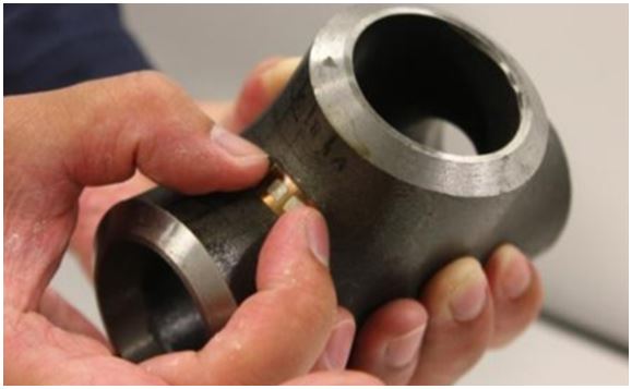
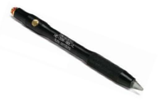
Fig.5 Measurement image of T-joint Fig.6 Small size UT sensor
Table1 Specification of complex shape mockup
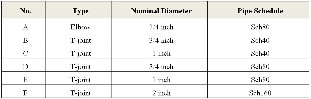
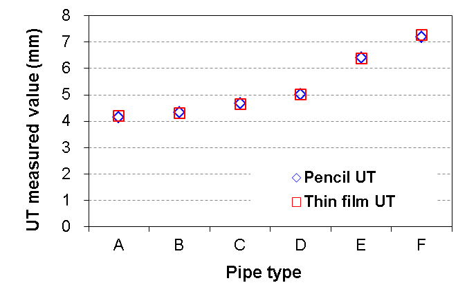
Fig.7 Measurement accuracy on complex shaped mockup
ii) Verification of high-temperature durability
In order to confirm high-temperature durability of the thin-film UT sensor, the thermal cycle test and the continuous thermal test were carried out.
The thermal cycling test was carried out between room temperature and 200 degrees C by turns. A thin-film UT sensor was attached to piping which has 5.9 mm thickness and it was verified that whether thin-film UT sensor can accurately measure the wall thickness or not after each thermal cycling. The test condition of thermal cycle test is shown in Table2. As shown in Fig.8, the sensor could work after ten heat cycles without the indication of sensor flaking caused by heat expansion.
The continuous thermal test was carried out at 200 degrees C and the measurement is still ongoing. As shown in Fig.9, there were not remarkable signal distortion, noise and remarkable attenuation of signal amplitude after two years heating. Based on these results, it is considered that thin-film UT sensor has good high-temperature durability.
Table2 Test condition of thermal cycle test
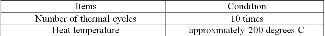
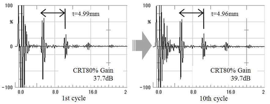
Fig.8. UT waveform of thermal cycle test
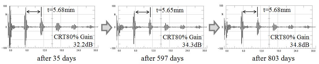
Fig.9 UT waveform of continuous thermal test
iii) Verification of high-temperature durability
In order to confirm irradiation durability of thin-film UT sensor, irradiation durability test was carried out. The test condition of irradiation is shown in Table3.
As shown in Fig.10, there were not remarkable signal distortion, noise and remarkable attenuation of signal amplitude after the irradiation test. 3300Gy is equivalent to the amount of irradiation for approximately 30 to 40 years on the surface of Main Coolant Pipes in nuclear power plant. Therefore, it is considered that thin-film UT sensor has long term applicability in nuclear power plant.
Table3 Test condition of irradiation
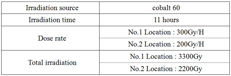
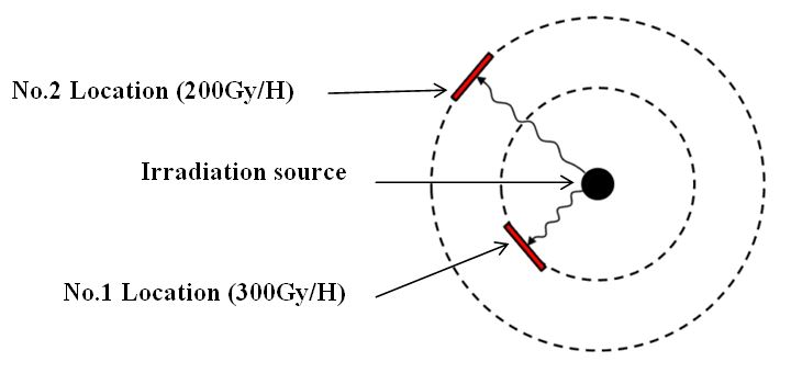
Fig.10 Irradiation layout
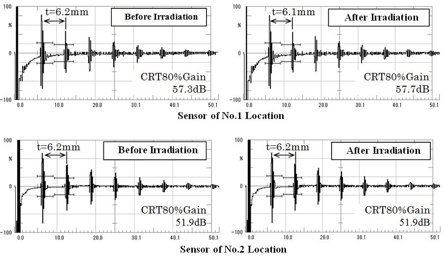
Fig.11 UT waveform of verification of irradiation durability
In order to confirm applicability to actual plant of the thin-film UT sensor, we carried out the field trial at nuclear power plant as shown in Table 4. We installed thin-film UT sensors (Fig.12) to the pipe of actual nuclear power plant.
An example of waveform is shown in Fig.13. There were not remarkable signal distortion and noise after test period of 4 months. As for two sensors, it was observed slightly attenuation. We consider that there is no issue in thin-film UT sensors and it was caused by changing of contact condition. There is an issue of install process and it needs to be modified for more stable measurement.
Table 4 Field trial condition
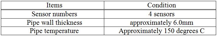
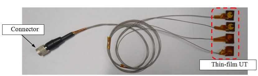
Fig.12 Thin-film UT sensor for field trial
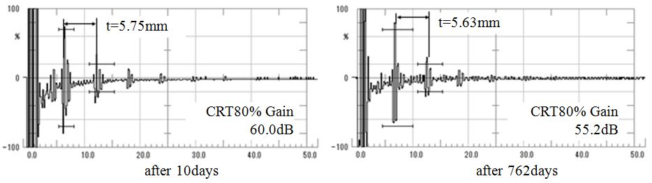
Fig.13. Waveform of field trial
(1) Alternative of periodic wall thickness measurement
- i) Thin-film UT sensor’s heat tolerance capability enables continuous setting under plant operation.
- ii) Wall thickness can be measured without additional work for heat insulator or scaffold.
- iii) More precise measurement thanks to stable position and condition because thin-film UT sensor is attached by adhesive material.
Periodical wall thickness measurement is carried out based on JSME S NH1/NG1 “Codes for Nuclear Generation Facilities –Rules on Pipe Wall Thinning Management for PWR Power Plants-” during outage. Thin-film UT sensor can be alternative method of periodic wall thickness measurement.
Configuration of periodic wall thickness measurement system is shown in Fig.14. Multiple thin-film UT sensors are attached under heat insulator for several years at measurement points. Periodical wall thickness measurement can be performed by just connecting measurement equipment via relay box.
There are following advantages for thin-film UT sensor.
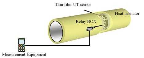
Fig.14 Periodical wall thickness measurement system using thin-film UT sensor
(2) Wall thinning monitoring
- ii) Better control of water quality and operating condition will become possible, because more precise understanding of the relationship between water condition and FAC will become possible.
Recently, the wall thinning suppressing by optimization of water quality or operation condition is carried out. Thin-film UT sensor enables understanding of efficiency of wall thinning suppressing because it enables measurement of wall thickness during plant operation.
Configuration of wall thinning monitoring system using thin-film UT sensor is shown in Fig.15.
Multiple thin-film UT sensors are attached under heat insulator for several years at measurement points. Furthermore, a permanent measurement system is set outside of heat insulator.
Thickness data can be acquired at arbitrary frequency and these data are transferred to data acquisition PC or are stored to permanent measurement system.
There are following advantages for thin-film UT sensor.
i) Thin-film UT sensor’s heat tolerance capability enables continuous monitoring under plant operation.
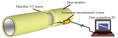
Fig.15 Wall thinning monitoring system using thin-film UT sensor
(3) Application to complex geometry
Wall thickness measurement of complex geometry such as elbow or T-joint is carried out during outage. On the other hand, stable measurement can’t be performed because of point contact in case of conventional UT sensor. Thin-film UT sensor had an advantage of stable measurement because it could fit the surface of complex geometry because of its flexibility.
7. Examples of Application
Thin-film UT sensor which is flexible and high temperature tolerant was developed. It was verified that thin-film UT sensor have high-measurement accuracy, high-temperature tolerant and irradiation durability. This thin-film UT sensor produces following advantage for pipe wall thinning management of nuclear power plant.
- Measurement becomes stable because of continuous attachment.
- Additional work for installation and removal becomes unnecessary because of continuous attachment.
- Measurement on complex geometry becomes possible because of the flexibility.
- The continuous wall thinning monitoring during plant operating becomes possible.
MHI will investigate the suitability to Japanese standard and would like to replace all manual thickness measurement to continuous monitoring using thin-film UT sensor in the future.
8. Reference
- [1] M. Kobayashi, Cheng-Kuei Jen, Daniel Levesque, “Flexible Ultrasonic Transducers”, IEEE Transactions on ultrasonics, and frequency control, Vol.52, No.8, August 2006.
- [2] K. T. Wu, C. K. Jen, M. Kobayashi, A. Blouin, “Integrated Piezoelectric Ultrasonic Receivers for Laser Ultrasound in Non-destructive Testing of Metals”, Journal of Nondestructive Evaluation (2011) 30:1-8
- [3] N. Fujita, I. Seki, T. Matsuura, Y. Yamamoto, M. Kurokawa, “Development of thickness measurement and thickness trend monitoring technology using high-temperature thin-film UT sensor”, Japan Society of Maintenology, Vol.10, July 2013.
- [4] T. Kodaira, I. Seki, T. Tsuruta, N. Kawase, T. Matsuura, Y. Yamamoto, S. Kawanami, “Monitoring of pipe wall thickness using high-temperature thin-film UT sensor”, 11th International Conference on Non Destructive Evaluation, May 2015.
- [5] T. Kodaira, Y. Yamamoto, T. Kimura, T. Tsuruta, I. Seki, “Wall thickness monitoring using high-temperature thin-film UT sensor”, JSNDI Fall Conference 2016, October 2016.
Japan Society of Maintenology (ejam@jsm.or.jp)