


| Vol.2 No.1 |
|||||||||||||||||||||||||||||
| Vol.2, No.2, NT24
|
|||||||||||||||||||||||||||||
Development of the advanced phased array UT technique for accurate sizing of cracks in the nozzle welding |
|||||||||||||||||||||||||||||
| Mitsubishi Heavy Industries, LTD. | |||||||||||||||||||||||||||||
KEYWORDS: |
|||||||||||||||||||||||||||||
| 1. Technical summary | |||||||||||||||||||||||||||||
| Classification (I: Inspection, II: Repair, III: Replacement, IV: Preventive Maintenance, V: Others) | |||||||||||||||||||||||||||||
|
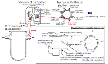
Recently, preventive maintenance tasks for welding of safe-end nozzles of reactor vessels(R/V) and steam generators(S/G) of PWRs in Japan had been carried out sequentially. Before the maintenance tasks, inspection services were carried out and several crack indications were found by eddy current testing (ECT). These indications were found in the welding which made by 600 series nickel base alloy and evaluated as stress corrosion cracks (SCC) which were oriented to the axial direction of the nozzle. Then investigations to evaluate the depth of cracks were carried out by ultrasonic testing (UT) from inner surface of the nozzles. However they were difficult to evaluate the depth of cracks due to the high attenuation of the ultrasonic propagation caused by large grain structure of welding. And also it was required high resolution near surface region for accurate sizing. Therefore development of advanced phased array UT techniques specialized for the sizing at this portion was carried out. Firstly simulations of the ultrasonic propagation in the welding were carried out to optimize beam profiles of phased array probes. Next prototype probes were manufactured and verification tests were conducted to evaluate the accuracy of depth sizing. It is shown that the developed techniques have high sizing accuracy for artificial stress corrosion cracks in the welding. | |||||||||||||||||||||||||||||
| 2. Scope | |||||||||||||||||||||||||||||
|
(1) Components: Safe-end of Reactor Vessel |
|||||||||||||||||||||||||||||
| 3. Features | |||||||||||||||||||||||||||||
|
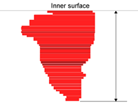
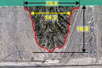
In 2008, a defect was detected by ECT in Dissimilar metal welding(DMW) of R/V safe-end at KEPCO Ohi unit3.The tip echo of the defect could not be detected by a conventional UT, so depth sizing of the defect was not carried out. The length of the defect and the tip is shorter than other defects. So that is the reason why tip echo could not be detected.
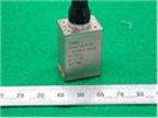
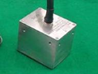
Fig.1 Actual defect profile of Reactor Vessel Sizing technique have been developed based on the Phased-array UT. For covering 40mm depth area, two kinds of the probes are developed for different depth areas.
Table1 Sizing Probe Specification
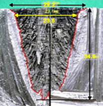
In order to evaluate the developed probes, artificial SCC which has imitated the actual plant defect had inserted a test block. From destructive examination results, artificial SCC has looked like actual SCC.
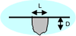
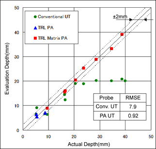
Fig. 2 Cross Section of SCC Test Piece Comparing the results of the defect sizing in the conventional probe and developed probe, the tip echo level of the developed probe is higher than that of conventional probe, especially for deep defects the developed probe can be confirmed better than conventional probes in sizing accuracy.
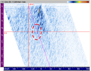
Fig.3 Test result for Deep SCC
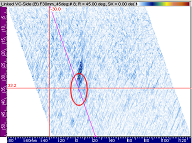
Fig. 4 Sizing Evaluation Figure 5 shows the B scope image and the movement of the wave pattern of the A scope for the SCC of 30mm depth data tested by TRL matrix PA. The arrow on the A scopes wave pattern shows the movement of the tip echo. |
|||||||||||||||||||||||||||||
| 4. Examples of Application | |||||||||||||||||||||||||||||
|
None |
|||||||||||||||||||||||||||||
| 5. Reference | |||||||||||||||||||||||||||||
|
|||||||||||||||||||||||||||||
| 6. Contact | |||||||||||||||||||||||||||||
| Japan Society of Maintenology (ejam@jsm.or.jp)
|
|||||||||||||||||||||||||||||
|
Vol.10 No.2(Aug) |
|
| < Other Issues | |
|---|---|
 |
A New Mechanical Condition-based Maintenance Technology Using Instrumented Indentation Technique |
 |
Survey robots for Fukushima Daiichi Nuclear Power Plant |

Contacts
(EJAM): ejam@jsm.or.jp
(JSM): secretariat@jsm.or.jp
HP: http://www.jsm.or.jp
(in English)
![]()