Search


Information
ICMST-Tohoku 2018
Oct. 23 - 26, 2018
Sendai, Japan
ICMST-Shenzhen 2016
Nov 1 - 4, 2016
Shenzhen, China
(EXIT THIS PAGE)
ICMST-Kobe 2014
Nov 2(Sun) - 5(Wed), 2014
Kobe, Japan
Nuclear Regulation Authority Outline of the New Safety Standards for Light Water Reactors for Electric Power Generation
For Public Comment
Outline of New Safety Standard (Design Basis)
For Public Comment
New Safety Standards (SA) Outline (Draft)
For Public Comment
Outline of New Safety Standard(Earthquake and Tsunami)(DRAFT)
Issues
 

Vol.10 No.2(Aug)
Vol.10 No.1(May)
Vol.9 No.4(Feb)
Vol.9 No.3(Nov)

< Other Issues


Occasional Topics
OTjapan Measures for Tsunami Striking Nuclear Power Station in Japan
Special Article: The Great Tohoku Earthquake (1)
OTjapan The Tragedy of “To Be” Principle in the Japanese Nuclear Industry
EJAMOT_CN3_Figure1_The_outside_view_of_CEFR OTChinaPlanning and Consideration on SFR R&D Activities in China
< All Occasional Topics

Featured Articles
EJAM7-3NT72 A New Mechanical Condition-based Maintenance Technology Using Instrumented Indentation Technique
EJAM7-3NT73 Survey robots for Fukushima Daiichi Nuclear Power Plant

JSM
Contacts
(EJAM): ejam@jsm.or.jp
(JSM): secretariat@jsm.or.jp
HP: http://www.jsm.or.jp
(in English)

 
Vol.2 No.1 previous GA 13 - AA 15 - SP2 (16 - 17 - 18 ) - NT 23 - 24 - 25 next Vol.2 No.3
Vol.2, No.2, NT23 EJAM(2-2-NT23) Ultrasonic integrity assessment for foundation bolts of nuclear power plants

Ultrasonic integrity assessment for foundation bolts of nuclear power plants

 
Hitachi, Ltd.
Hitachi-GE Nuclear Energy, Ltd.
The Tokyo Electric Power Co, Inc.
 

KEYWORDS:
Bolt inspection, ultrasonic testing, phased array, seismic safety, focal zone

 
1. Technical summary
 
Classification
(I: Inspection, II: Repair, III: Replacement, IV: Preventive Maintenance, V: Others)
 

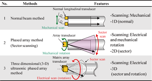
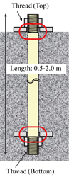
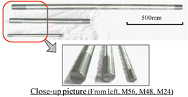
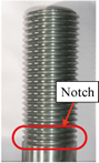
Integrity assessment for nuclear power plant major components is essential for aging management and seismic safety evaluation. Foundation bolts are support structures important to structural integrity. Therefore ultrasonic testing (UT) as volumetric inspection method is effective for integrity assessment of the bolts. The foundation bolts in nuclear power plants have various lengths and diameters, and one end of the bolt is embedded in concrete. An ultrasonic transducer is coupled to the end of the bolt (Fig.1). Aperture of the transducer is optimized based on length and diameter of the bolt. Ultrasonic beam is scanned for covering inspection area, both threads at the top and the bottom. Validity of conventional UT method (normal beam longitudinal wave technique) and phased array UT methods with different beam scanning (2-D and 3-D phased arrays), listed in Table.1, is confirmed through experiments of foundation bolt test pieces (Fig.2).

Table.1 Ultrasonic testing methods for bolt inspection

EJAM2-2NT23_Table.1_Ultrasonic_testing_methods_for_bolt_inspection

EJAM2-2NT23_Fig.1a_Ultrasonic_bolt_inspection EJAM2-2NT23_Fig.1b_Ultrasonic_bolt_inspection
(a) Schematic view (b) Ultrasonic field in bolt

Fig.1 Ultrasonic bolt inspection

EJAM2-2NT23_Fig.2a_Test_pieces_of_foundation_bolts EJAM2-2NT23_Fig.2b_Test_pieces_of_foundation_bolts
(a) Photo of foundation bolts (b) Artificial defect (notch)

Fig.2 Test pieces of foundation bolts

2. Scope

(1) Components: Foundation bolt (length: 0.5-2.0 m, diameter: 20-60mm).
(2) Inspection Area: Top and bottom threads.
(3) Materials: Carbon steels.
(4) Condition: UT transducer coupled to one end of the bolt.

3. Features
  • Conventional UT method: Position of the UT transducer is scanned mechanically on the end face. Inspection data is displayed as A-scan representation, ultrasonic intensity as a function of received time (Fig.3)
EJAM2-2NT23_Fig.3a_Results_of_longitudinal_normal_beam_method EJAM2-2NT23_Fig.3b_Results_of_longitudinal_normal_beam_method
(a) Top thread: 1.6mm notch (b) Bottom thread: 1.6mm notch

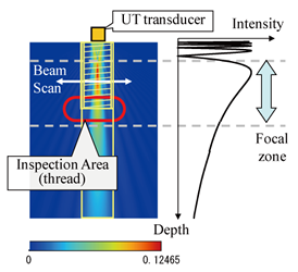
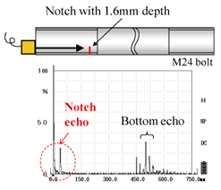
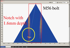
Fig.3 Results of longitudinal normal beam method (test piece)

  • Two-dimensional phased array method: Angled ultrasonic beam is steered electrically and the array transducer is rotated mechanically. Inspection data is represented as B-scan image, cross-section view (Fig4.).
EJAM2-2NT23_Fig.4a_Results_of_two-dimensional_phased_array_method EJAM2-2NT23_Fig.4b_Results_of_two-dimensional_phased_array_method
(a) Top thread: No notch (b) Top thread: 1.6mm notch

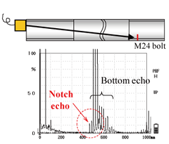
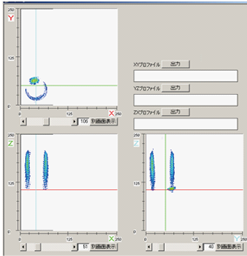
Fig.4 Results of two-dimensional phased array method (test piece)

  • Three-dimensional phased array method: Beam steering and rotating is scanned electrically at real time. The acquired data is processed to the three-dimensional voxel image (Fig.5).
EJAM2-2NT23_Fig.5_Results_of_three-dimensional_phased_array_method

このページのコンテンツには、Adobe Flash Player の最新バージョンが必要です。

Adobe Flash Player を取得

(a) 3-D view
EJAM2-2NT23_Fig.5b_Results_of_three-dimensional_phased_array_method
(b) Cross section view

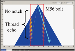
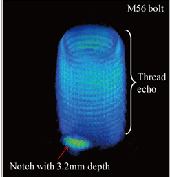
Fig.5 Results of three-dimensional phased array method (test piece)

4. Examples of Application
  • All notches with depth of 1.6mm and 3.2mm are detected for the conventional method, 2-D Phased array, and 3-D phased array method.
  • Visualization through the phased array methods improves flaw recognition.
  • 3-D phased array method provides quick and wide-region imaging covering whole inspection area.
5. Reference
  1. [1] S. Kitazawa, N, Kono, A. Baba, Y. Adachi, M. Odakura, and O, Kikuchi; "Three-dimensional visualization and evaluation techniques for volumetrically scanned data of ultrasonic phased arrays", Insight, vol.52, No.4, 2010
6. Contact
Japan Society of Maintenology (ejam@jsm.or.jp)
backtotop