


Classification
5 - B (SCC Mitigation Method)
The stress corrosion cracking (SCC) susceptibility of boiling water reactor (BWR) components, such as stainless steel and Ni base alloy materials, is mitigated by the reduction of electrochemical potential (ECP). Current mitigation methods are hydrogen water chemistry (HWC) and noble metal chemical addition (NMCA). In these methods ECP reduction depends on the decrease of dissolved oxygen and hydrogen peroxide concentration, continuous hydrogen injection is necessary and the ECP reduction effect varies the location in the reactor and hydrogen injection rate.
The TiO2 technique reduces the ECP of the components to mitigate the SCC without hydrogen injection. The ECP reduction is caused by oxidation of water on the surface of the TiO2 by photo-exciting reaction under ultra violet light irradiation (Cherenkov radiation in the operating reactor) regardless of the water chemistry. Therefore the ECP reduction effectively occur whole inside the reactor vessel throughout the operation. TiO2 deposition (treatment) on the reactor internals is made by TiO2 dilute solution addition in operation or at refueling outage (Fig.1). In reactor components, where Cherenkov radiation reaches, ECP shows -400mV or less independent of dissolved oxygen concentration in the reactor water. So far, no significant issue of fuel was found by PIE test of TiO2 deposited fuel under a simulated BWR condition [1].
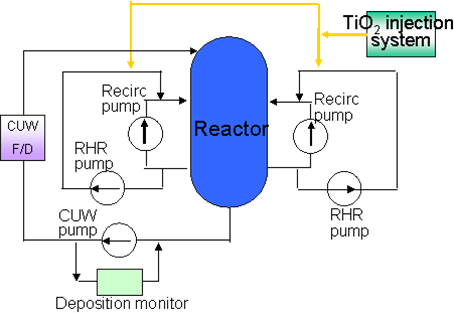
Fig.1 Schematic diagram of TiO2 injection
Phase 2 : Industrial Confirmation Phase
The principal of TiO2 technique is shown in Fig.2. Generally, when metal oxidation occurs, the electron in base metal is released (anodic reaction) and exhausted by cathodic reaction of dissolved oxygen. On the other hand, TiO2 is an n-type semiconductor and it oxidizes H2O and generates anodic current due to photo-excitation reaction under the ultraviolet light irradiation with wavelength of less than 400nm in the water. Cherenkov irradiation which is generated by the interaction between water and radiation is available in reactor. Therefore, this reaction suppresses corrosion reaction of metal oxidation.
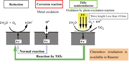
Fig.2 The principal of TiO2 technique
Figure 3 shows the anodic polarization curves determined for the Nb-doped TiO2 single crystal electrode in a deaerated 50mmol/L Na2SO4 solution environment at 275°C under UV irradiation and no irradiation (dark) condition [2]. The anodic current density increases from 10-2A/m2 at -0.4V (SHE) and saturates about 45A/m2 at more than 0.2V (SHE). It is consistent with the report by Fukaya et al [3] . The anodic current density is higher than that of Type 304 stainless steel at > –0.3V (vs.SHE). It implies the possibility that the ECP of the TiO2 coated stainless steel decreases to about –0.3V (vs.SHE) under UV irradiation in high temperature pure water containing dissolved oxygen. The anodic polarization curve measurement was conducted at the sweeping speed of 20mV/min.
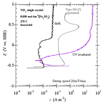
Fig.3 Anodic polarization curve of Nb-doped TiO2 single crystal under UV irradiation
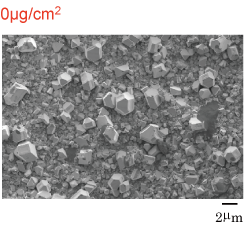
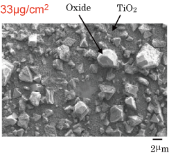
SEM observation of the surface the Type 304 stainless steel specimens after prefilming in simulating HWC condition for 500 hours and TiO2 treatment are shown in figure 4 [2]. As the deposited TiO2 on the surface of the specimen was very fine and thin, acceleration voltage for the SEM observation was reduced as low as 0.40kV to observe the deposited TiO2. These specimens were prefilmed in simulated HWC condition for 500 hours before the TiO2 coating.
(a) TiO2 untreated specimen
Large size particles (about 2µm) and small size particles (<1µm) were observed. By the EDX analysis it was determined that the large size particle was Fe rich oxide with Ni and small size particle was Cr rich oxide with Fe.
(b) TiO2 deposited specimen by chemical injection
33µg/cm2 TiO2 was deposited on the specimen. The fine TiO2 particles were uniformly deposited on the surface as well as the spray coated specimen. Compared with the spray coating, TiO2 deposition by the chemical injection method seemed to be thinner for the sample but the particles were distributed well on and among the oxides.
(a) TiO2 untreated specimen
Large and small size oxides exist.
(b) TiO2 treated specimen
by chemical injection method
Figure 5 shows the ECP behaviors of the rutile/anatase mixture TiO2 treated 316L stainless and alloy 600 in NWC reactor water after 2100 hours of reactor water exposure in 1100MWe plant [4]. The rutile/anatase mixture type TiO2 treatment specimen showed ECP reduction under UV irradiation.
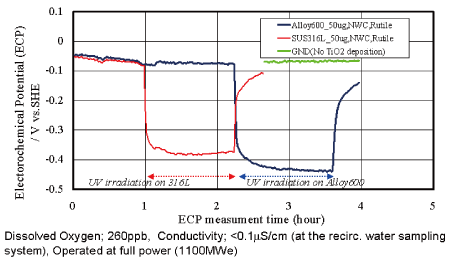
Fig.5 ECP behaviour of TiO2 (rutile/anatase mixture)-treated 316L SS and Alloy 600 in NWC reactor water, after 2100 hours of exposure
In-core and out-of-core ECP measurements of TiO2 treated materials were performed during reactor operation in the Halden reactor [5]. ECP were measured by Fe/Fe3O4 and Pt electrodes as a reference electrode. Test loop was prefilmed at 288 C with 10 ppm dissolved oxygen for 10 days. The reactor was operated at full power (15MW) during the ECP measurement tests. Fig.6 shows ECP measurement results of in-core and out-of-core stainless in the Halden reactor loop. The in-core ECP showed the SCC mitigation potential even in oxygenated condition in reactor position where the Cherenkov radiation was expected.
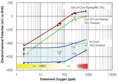
Fig.6 ECP measurement results of in-core and out-of-core stainless in the Halden reactor loop
TiO2 injection was performed successfully at Fukushima 2 unit 1 in June 2010. TiO2 solution was injected into both of RHR piping during shutdown at around 150°C (Fig.1).
TiO2 on-line injection (in operation) method will be developed soon.
- [1] Y.Ishii et. al, "The Effect of TiO2 on corrosion Behavior of Zircaloy-2 Fuel Cladding" 2005 Water Reactor Fuel Performance Meeting, AESJ, October 2-6, 2005, Kyoto, Japan.
- [2]K.Takamori et. al, "Corrosion Mitigation of BWR Structural Materials by the Photoelectric Method with TiO2 - A SCC Mitigation Technique and its Feasibility Evaluation -," 12th International Conference on Environmental Degradation of Materials in Nuclear Power Systems-Water Reactors, TMS 2005.
- [3]Y.Fukaya et.al, "Photoelectrical Protection of Stainless Alloys in BWR Primary Coolant Environment", 10th International Conference on Environmental Degradation of Materials in Nuclear Power Systems-Water Reactors, NACE 2001.
- [4]K.Takamori et. al, "Development of BWR Components SCC Mitigation Method by The TiO2 Treating Technique", 13th International Conference on Environmental Degradation of Materials in Nuclear Power Systems-Water Reactors, TMS 2007.
- [5]J.Suzuki et. al, "Development of SCC Mitigation Method in BWR Plant by TiO2 Technique", 15th International Conference on Nuclear Engineering, April 22-26, 2007, Nagoya, Japan.
Japan Society of Maintenology (ejam@jsm.or.jp)