


MITSUBISHI HEAVY INDUSTRIES, LTD. (MHI)
THE JAPAN ATOMIC POWER COMPANY (JAPC)
Vol.2, No.3, NT26
OUTER SURFACE IRRADIATED LASER STRESS IMPROVEMENT PROCESS (L-SIP) APPLIED TO PRESSURIZER AS RESIDUAL STRESS IMPROVEMENT METHOD
1. Technical summary
Classification
5 - B (Improvement of degradation mode)
Improvement of residual stress is effective in a countermeasure to deal with the stress corrosion cracks (SCC) in pipe welds. After irradiating laser beam around the welds of steel pipe, L-SIP is to improve inner surface residual stress from tensile to compressive by utilizing the temperature differences between inner and outer surface.
In order to improve residual stress, some ways of peening are applied. In the welds of steel pipes, it is often impossible to apply them to inner surface of pipes where stress corrosion crack occurs due to the inaccessibility.
L-SIP was applied to the nuclear power plant in order to improve inner residual stress of pressurizer nozzle for the first time in the world in 2007.
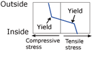
When outer surface of steel pipe is irradiated with laser beam, the temperature of outer surface rises as shown in Fig. 1. If heating time is short enough, the temperature of inner surface does not rise, and the temperature difference generates between inside and outside. Due to the difference of thermal expansion between inside and outside, compressive stress occurs to the outside and tensile stress occurs to the inside. In case that the temperature difference is large enough, plastic deformation occurs in the inside and outside of the material. When laser irradiation is stopped thereafter, the material is cooled. By the time there is no temperature difference between inside and outside, a compressive stress occurs in the inside affected by tensile plastic deformation when heated. Residual stress can be improved this way.
This is the method of improving residual stresses all around by moving the region irradiated by laser beam on the outer surface in the circumference direction. In addition, temperature increase by high energy laser is so high that inside water cooling can be omitted especially for a small pipe or nozzle.
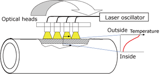
Fig. 1 (a) Pattern diagram of laser stress improvement process
| Temperature distribution | Stress | |
|---|---|---|
| During irradiation | 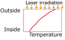 |
 |
| After cooling | 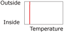 |
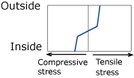 |
Fig. 1 (b) Pattern diagrams of plate thickness internal temperature distribution and stress distribution during irradiation and after cooling
2. Development phase
Phase 2 : Industrial Confirmation Phase
- Its effectiveness and influence were confirmed by a third party in industry.
- L-SIP was applied to the nuclear power plant for the first time in the world in 2007.
3. Scope
- (1) Components: Nozzle or pipe (When anything cannot approach from inside.)
- (2) Location: Dissimilar Metal Weld of nozzle or Similar Metal Weld of pipe
- (3) Material:
Alloy600/690 (Nickel based alloy) for Dissimilar Metal Weld
Austenitic stainless steel for Similar Metal Weld
- (4) Condition: Water or air for inner cooling
4. Features
- (1) Even if it is impossible to access inner surface of nozzle or pipe, improvement of residual stress is possible by L-SIP.
- (2) Laser power is so high that inside water cooling can be omitted especially for a small pipe or nozzle.
- (3) Laser power is so high that L-SIP is applicable for a thin pipe.
- (4) Since inside water cooling is unnecessary, L-SIP is applicable for a pipe with thermal sleeve.
- (5) Optical heads is so small and light that installation time of equipment is very short.
Supplementary explanation
(a) Material
Surge nozzle on the bottom of pressurizer, the spray nozzle, safety valve nozzles and relief valve nozzle on the top are made of low alloy steel (LAS) and its safe-end of stainless steel. The nozzle and safe-end are jointed with dissimilar metal weld, Alloy 600/690. (Fig.2,3)
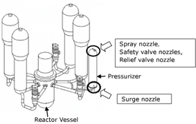
Fig.2 Reactor Coolant System (RCS) of PWR
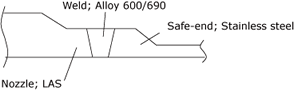
Fig.3 Schematic diagram of the nozzles
(b) Laser Oscillator
Type of the laser is fiber laser that is one of the near infrared rays, and the total capacity of five oscillators’ output is approximately 38kW. The five oscillators in two containers are installed out of radio active control area, and can be controlled with main controller installed in containment vessel. (Fig.4)
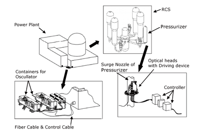
Fig. 4 Schematic Diagram of L-SIP system on site
(c) Laser Fiber
The laser fiber cable transmits the laser from oscillators to optical heads, 8 fibers are contained in it and its flexible cover protects them. The cable is flexible enough to be laid from outside to pressurizer surge nozzle through the penetration of the building although its length is approximately 300 meters. (Fig.4)
(d) Optical Head with driving device
The optical heads are installed on driving device attached to nozzle. Each optical head is connected with a fiber and cooled with circulation water. For safety reason, slight reflected light inside an optical head is monitored during L-SIP, and in case that the reflection level rapidly decreases the system shall be shut down automatically because of the possibility of the damage of fiber cable.
The driving device is attached to pipe or pressurizer, rotates the optical heads around the nozzle and also controls the irradiating distance. This driving device can be controlled remotely.
(e) Irradiation
Test irradiation was performed to a mock-up nozzle to obtain parameters for the actual plant in Kobe. The regular irradiation was performed to the pressurizer surge nozzle on TSURUGA unit 2 in 2007 and to the other nozzles in 2010. (Fig. 5, 6)
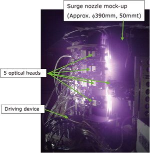
Fig. 5 Test irradiation to a surge nozzle mock-up in KOBE
Fig. 6 Actual irradiation to a surge nozzle on TSURUGA unit 2
As a result, it turned out that all the maximum temperatures reached to the required condition, approximately 500°C, and each heat-up time was short enough in regular irradiation, so it was confirmed that this L-SIP application met required conditions and was successfully completed.
As a new improvement method for the residual stresses in the welds of pipes and nozzles, L-SIP has been successfully applied to PWR pressurizer nozzles.
5. Examples of Application
- (1)Pressurizer surge nozzle on TSURUGA unit 2 in 2007
- (2)Pressurizer spray, safety valve and relief valve nozzles on TSURUGA unit 2 in 2010
6. Reference
- [1]N. Sugimoto et al.: ICONE14-89375, 2006
- [2]Takeshi Ueda et al.: ICONE16-48379, 2008
7. Contact
Japan Society of Maintenology (ejam@jsm.or.jp)