


| OT1 - OT2 - OT3 - OT4 - OT5 - OT6 - OT7 - OT8 - OT9 - OT10.. All OTs |
| Occasional Topics |
| OT6 (09-10-28) |
| Hamaoka Unit #5-nuclear Turbine Incident and its Countermeasure |
| Tateki Nakamura, Hitachi, Ltd. Power Systems, Hitachi works |
| KEYWORDS: Turbine blade, High cycle fatigue, Random vibration, Steam-flash back |
1. Outline of the Incident
On June 15, 2006, Hamaoka Nuclear Power Station Unit 5 was in operation at constant thermal output when the alarm “Excessive Turbine Vibration” was initiated . As a result, the turbine tripped and the reactor was shut down automatically. Upon opening the LP turbine B (BLP) casing, it was found that a blade of the L-2 stage, the third stage from the exhaust, was detached from the rotor.
Detailed inspections revealed that the forks and pins of the L-2 stage blade root structure were damaged. Further examination of its fracture surfaces confirmed a sign of high-cycle fatigue. Hitachi responded to the blade failure by applying its resources to define, diagnose and resolve the problem for the customer. In February 2007, eight months after the incident, Hamaoka # 5 restarted the turbine with a pressure plate instead of the L-2 blade. 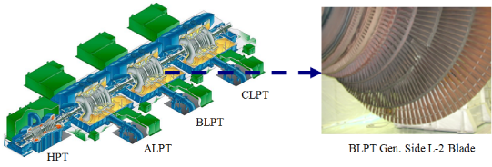 Figure 1 Hamaoka #5 Blade Failure 2. Root Cause Detailed damage analysis revealed that the high-cycle fatigue was due to high unexpected stress caused by superposition of Random Vibrations and Flashback Vibrations during low load test operation.
2.1 Random Vibrations Random Vibrations are irregular oscillations that occur in blades, caused by steam turbulence within the turbine. This happens when the turbine is under no load or at low load operation. According to Hitachi design experience, Random Vibrations are frequently found in turbine stages L-0 and L-1 and are taken into consideration in the blade design process. Simulation of internal flow based on both CFD and testing at Hitachi’s test facility confirmed that due to Hamaoka’s large steam turbine capacity the L-2 blades are also potentially subject to Random Vibration force, a phenomenon that had not been observed on other Hitachi steam turbines. (Figure 2 & 3).
2.2 Flashback Vibrations Flashback Vibrations are caused by wet steam that enters the turbine through the feedwater extraction nozzles during load rejection. This reverse flow of extraction steam into the turbine is caused by pressure drop in the turbine that occurs when the steam flow is suddenly stopped or significantly reduced. In Hamaoka Unit #5, the feedwater heater #2 steam extraction piping is located just upstream of the L-2 blades, and hence, the L-2 stage was subject to Flashback Vibrations.
2.3 Superposition of Random and Flashback Vibrations Simulation of the Hamaoka #5 steam turbine’s internal flow by CFD and testing at Hitachi’s test facility revealed Random Vibration force or Flashback Vibration force alone was not large enough to cause the severe blade damage. However, Flashback Vibrations and Random Vibrations could occur simultaneously and superposition of both vibration forces could cause unexpected and excessive stress to the blade fork area. These phenomena were not taken into consideration during the detailed design. Therefore, this strong, combined vibration force to the L-2 blades was concluded to result in fatigue cracking of the blade fork during commissioning and subsequently progress to the blades break from the turbine rotor disc. (Figure 2).
_Flow_patterns_by_CFD(Random_vortex_and_turbulence).png) Random vortex and turbulence _Flow_patterns_by_CFD(Random_plus_Flashback).png) Random plus Flashback Figure 2 Flow patterns by CFD 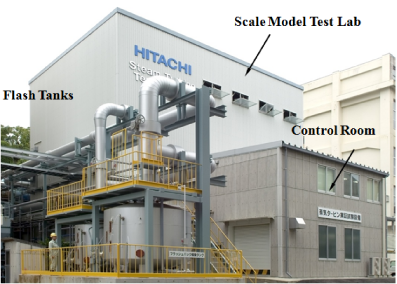 Figure 3 Steam turbine test facility
3. Damage Mechanism
The initial turbine operation, in particular 20% load rejection test, followed by no-load turbine operation, could be considered to lead to special conditions that Random Vibrations and Flashback Vibrations occur simultaneously. It is highly likely that the fatigue cracking in the L-2 blade root could be initiated in these initial functional tests because the cumulative fatigue ratio exceeds the critical fatigue ratio in the fork area of the blades.
After the initiation of the fatigue crack, the stress due to Random Vibrations at low load operation and Flashback Vibrations at the load rejection tests caused further propagation of the initiated cracks, and finally, on June 15, 2006 the residual area of the fork was unable to withstand the centrifugal force imposed on the blades, and fork and pins ruptured. 4. Conclusion, Improved Design
As a result of the Hamaoka #5 experience, a new set of L-2 stage blades was developed with higher damping structure and optimum rigidity to withstand both Random Vibrations and Flashback Vibrations during low load operation and load rejection, respectively. Design improvements of blade structures and Continuous Cover Blade (CCB) have been reflected to Hitachi’s standard turbine blade design.
Scale model turbine testing and full size rotation testing based on the improved design were completed and the reliability of the new design has been verified. Figure 4 shows a drawing of the new L-2 Continuous Cover Blades. 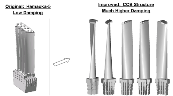 Figure 4 New L-2 Blade with Continuous Cover Blade Structure |
|
Vol.10 No.2(Aug) |
|
| < Other Issues | |
|---|---|
 |
A New Mechanical Condition-based Maintenance Technology Using Instrumented Indentation Technique |
 |
Survey robots for Fukushima Daiichi Nuclear Power Plant |

Contacts
(EJAM): ejam@jsm.or.jp
(JSM): secretariat@jsm.or.jp
HP: http://www.jsm.or.jp
(in English)
![]()