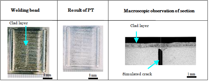
Laser machining is considered to be the best tool for works at remotely controlled and narrow space, because the reaction force of this method is rather small. Seal-welding method overlaying near location of crack is outlined as a post maintenance method utilizing characteristics of laser beam. Underwater laser seal-welding is possible to control heat input to be less than conventional methods and has a merit as Helium embrittlement measure. Helium is one of transmutation products by neutron irradiation. Using a thin type of welding head which is developed for narrow space, underwater laser seal-welding of horizontal position was performed on the surface with a simulated crack of 0.3 mm in opening width, 30mm in depth and 20mm in length under the weld condition of heat input of 0.5kJ/cm, wire supply rate of 1.2 m/min, and shield gas rate of 951/min. SUS304L was used as base metal, and Y308L welding wire of 0.6 mm diameter was used. A example of underwater laser welding test result is shown in Fig. 2.
|
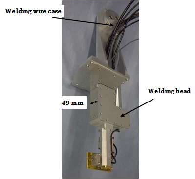
Fig. 1 Appearance of welding head
|
|
Fig. 2 Results of laser seal welding test |
In this case, a good weld bead was obtained, no indication was found by liquid penetration test, and also it is confirmed that the simulated crack can be sealed by weld cladding from macroscopic section observation. In this underwater welding technique, shield gas forms partial inert gas environment around a simulated crack, and expel water composition inside the simulated crack. Solidification of melted weld metal composed of wire and base metal occurs on the simulated crack and the seal is done.
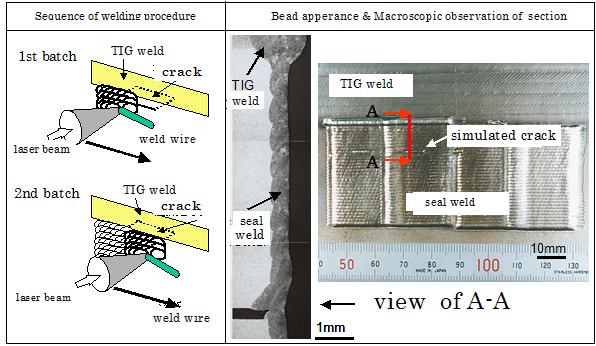
In the next step, seal welding was done using a mockup simulating outer curvature radius of shroud. SUS316L was used as base metal and Y308L was used as a welding wire. TIG weld was made on the mockup and simulated crack of 0.3 mm in width, 5mm in depth, 30 mm in length was machined at the location of 10 cm downward from the weld. The welding condition at that time was 0.75kJ/cm of heat input, 0.8 m/min of wire supplying rate, and 95 l/min of flow rate of sealed gas. In Fig.3, a sequence of welding process, appearance of location of weld after welding and results of macro scale observation of the section of test parts. In order to overlay in broad area, welding of 30 mm x 50 mm per one batch was superimposed and repeated. |
|
Fig. 3 Mockup test results |
|


