


The Japan Atomic Power Company
Tepco Systems Corporation
Vol.3, No.4, NT41
Simplified Evaluation Method of Strain Rate Being Generated on Structural Materials during Plant Start-up
1. Technical summary
Classification
3 - A
As previously reported in NT-37[1], it is important for mitigation of Stress Corrosion Cracking (SCC) to evaluate strain rate of structural materials induced by transient loading such as plant start-up. Theoretical backgrounds are given in reference [2] concerning possible severe conditions for susceptible materials to SCC from the viewpoints of both mechanical and environmental loading during such transient processes.
Previous report NT-37 showed a simplified evaluation method of strain rate based on Green’s function for some typical components like core shroud, shroud support, PLR piping, and so on. Though the method provided an effective tool for quick calculation of strain rate with varying pressure and temperature conditions, scope of application was limited to an identical components configuration of an identical Nuclear Power Plant (NPP). Because the calculation results were derived from superposition of response outputs for loading inputs based on pre-calculated response for the unit step loading. If a tool user wants to apply the method to another NPP, he has to re-calculate the response to the unit step loading. This means the user should perform FEM model making for each NPPs that he wants to evaluate.
This report provides a more generated, extended method of strain rate evaluation, based on simplification of shell calculation. The cylindrical shell function method was applied, assuming symmetric distribution of temperature and pressure action. As structures concerned, for example, the core shroud have stepped-cylindrical shape, two and three elements of multi-element cylindrical shell models were developed. Figure 1 shows how to analyze the strain rate by using two-element cylindrical shell model. Thermal and pressure load are given to two shell models individually. Then the external load M01and Q01, bending moment and shear force applied at the edge of Shell 1, M02 and Q02 at the edge of Shell 2 are added with ⊿M0 and ⊿Q0, to balance the deflection and deflection angle to be in common at the edge of both shells.
As for a three-element shell model, the central cross section should be the center of the third shell shown in Fig. 2. Shell 1 and Shell 2 are assumed to have the half part of Shell 3 (Weld) in common, respectively. After the external loads are applied, similarly to the two-element shell model, additional components ⊿M0 and ⊿Q0 are given to the M01, Q01 and M02, Q02 as shown in Fig. 2.
This is the method of improving residual stresses all around by moving the region irradiated by laser beam on the outer surface in the circumference direction. In addition, temperature increase by high energy laser is so high that inside water cooling can be omitted especially for a small pipe or nozzle.


Fig. 1 Method for analyzing two-element cylindrical shell model


Fig. 2 Method for analyzing three-element cylindrical shell model
2. Development phase
Phase 1 : Research and Development Phase
3. Scope
- (1) Components: Vessels, reactor internals and piping which can be modeled by simple cylindrical shell
Examples
Primary loop re-circulation lines in BWRs
Shroud support in BWRs
Lower shroud in BWRs
Inlet line of steam generators in PWRs
Bottom mounted instrumentations in PWRs
- (2) Location: Weld joints
- (3) Material:
Regardless of material
- (4) Condition: Arbitrary pressure and temperature
4. Features
- • Easy and High-Speed
The simplified strain rate assessment tool is developed on the platform of Microsoft® Excel®, which is user-friendly, familiar and easy to learn. The screenshot of this tool is shown in Fig.3. This tool enables the user to calculate the strain rate in just a few steps.
In the first step, the user fills arbitrary pressure and temperature histories in the spreadsheet, and presses the button “Save Input File” and “Execution”. Then, strain rate calculation program runs in background and calculation results of the strain rate are stored in output files.
In the second step, the user presses the button “Post processing”. Then, calculation results of strain rate are stored and graphs of strain rate history are displayed on the Excel sheet as shown in Fig.4. This tool enables us to check easily and quickly the strain rate in an arbitrary plant operation procedure.
- • Useful for determining better plant operation procedure
This tool can calculate the strain rate easily and quickly as above described. Therefore, the tool can help us to develop better plant operating procedures, with lower susceptibility to SCC.
- • High-Accuracy
To verify the simplified strain rate assessment tool, the strain rate in the plant start-up condition is calculated using this tool. See the chapter 5, “Example(s) of Application”.
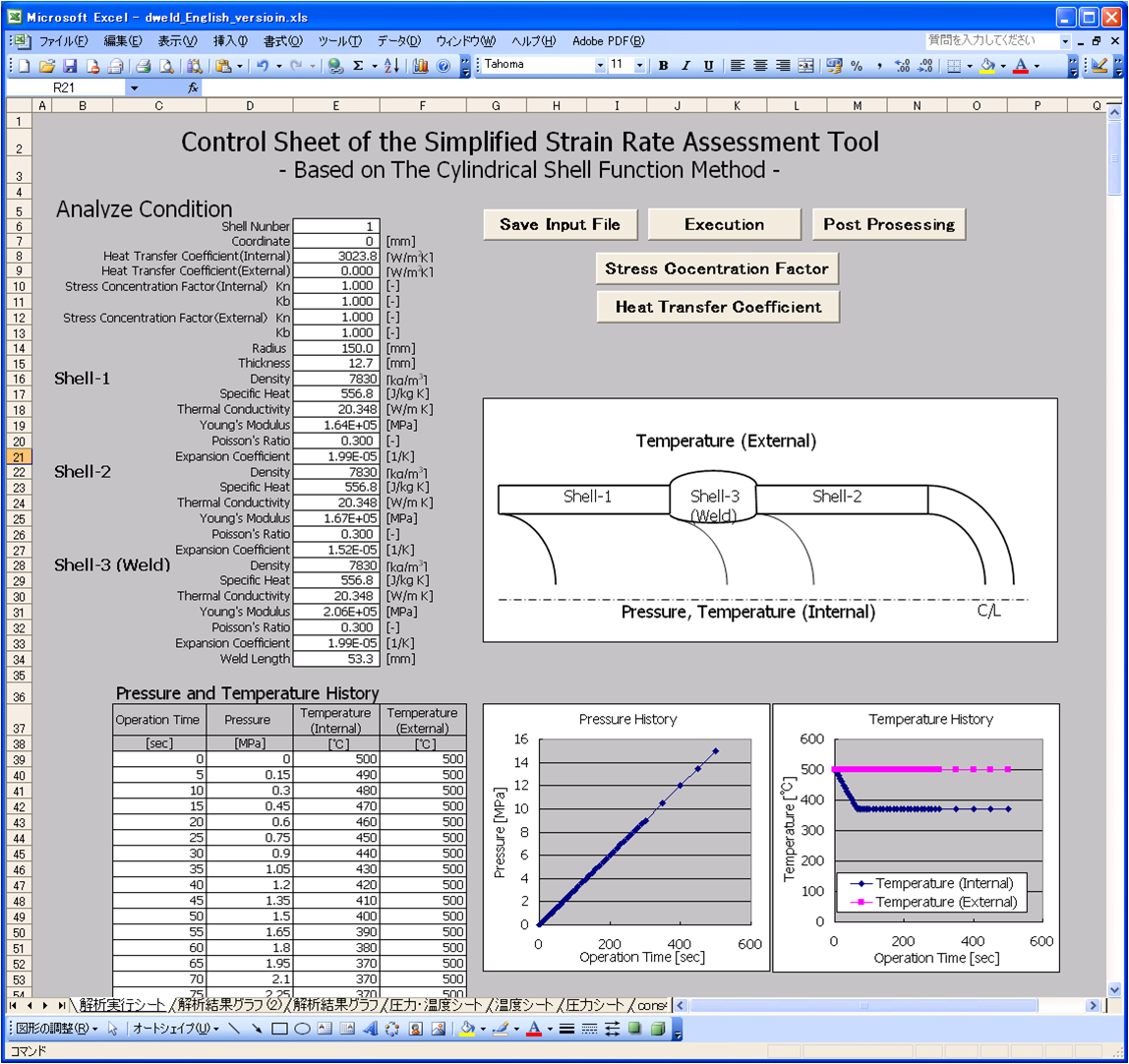
Fig.3 Screenshot of the simplified strain rate assessment tool (Control sheet)

Fig.4 Screenshot of the simplified strain rate assessment tool (Graph sheet)
5. Examples of Application
Finite Element Method computation for typical configuration and loading condition was performed to verify the simplified evaluation program. A stepped cylinder with 1056mm inner diameter and 800mm length shown in Fig. 5 was taken as an example to compute strain rate for the inner fluid temperature history T(t) and internal pressure history p(t). A ramp change was given as T(t) from 20℃ to 150℃ with 100 sec, and p(t) was given as proportional to T(t) by setting 0MPa at 20℃, and 10MPa at 150℃. Material and heat transfer properties used for computation are shown in Table 1.
Figure 6 shows the comparison of strain rate on the inside surface at the stepped position of a cylinder evaluated by the simplified shell model with FEM computational result. The simplified model gives approximately within 1.5 times of FEM computational result. The difference from FEM computation is considered to result in the assumption of replacement for simplification of temperature and internal pressure loading with bending moment and shear force at the center line of the shell.
It would be useful to apply this simplified evaluation program to an approximate estimation for prompt use or parametric survey to determine some design parameters with knowing its accuracy.
Table 1 Material and heat transfer properties


Fig.5 FEM Computation Model for Verification

A1 (Internal Surface) Evaluation Point
Fig.6 Comparison of Strain rate Evaluated by Simplified Shell Model with FEM Computation
6. Reference
- [1]EJAM NT-37, Strain Rate Evaluation of some Typical Nuclear Power Plant Components during Plant Operation, The Japan Atomic Power Company and Tepco Systems Corporation, August 2011.
- [2]A. Abe, H. Tobita, N. Nagata, K. Dozaki and H. Takiguchi, Mitigation of SCC Initiation on BWR Core Internals by Means of Hydrogen Water Chemistry During Start-Up, ANS, Nuclear Science and Engineering: 149, pp312-324, 2005
- [3]K. Dozaki, H. Chitose, H. Ogawa, and H. Machida, Strain Rate Evaluation of Some Typical Nuclear Power Plant Components During Plant Operation, Proc. of ASME PVP-2010, July18-22, 2010
- [4]K. Dozaki, H. Machida, O. Tsuzuki, H. Ogawa, H. Chitose, Simplified Evaluation Method of Strain Rate Being Generated on Structural Materials During Plant Start-up, ICONE 19, Osaka Univ., October 24-25, 2011.
*July 22,2013 Revised
7. Contact
Japan Society of Maintenology (ejam@jsm.or.jp)