


Classification
5 - A :Improvement
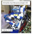
It is reported that many Boiling Water Reactors (BWRs) are experiencing damage of jet pumps by flow-induced vibration. The jet pump has a small gap known as slip joint between an inlet mixer and a diffuser to allow thermal expansion in operating condition. Differential pressure between inside and outside of the jet pump (slip joint differential pressure) creates a leakage flow at the slip joint. In rare cases, the leakage flow causes self-excited vibration called leakage-flow-induced vibration and damages to the jet pump. In the U.S., some BWR plants are allowed to be operated under extended power uprating condition by increasing core flow rate. In other cases, they are infrequently operated using only one primary loop recirculation system (single loop operation). These operating conditions increase risk of leakage-flow-induced vibration, because the power uprating condition increases the leakage flow at the slip joint and the single loop operation causes regurgitation of the leakage flow different from normal operating condition. One of methods for preventing the leakage-flow-induced vibration is holding down or immobilizing the inlet mixer to the diffuser more mechanically tight. However, this may cause the loss of the original function of the slip joint, that is, allowing the thermal expansion. To solve this problem, a new method eliminating root cause of the vibration has developed. This method is to stabilize the leakage flow by extending the gap flow passage of the slip joint. It does not require disassembly of the equipment and can be achieved in short construction period. In this paper, concept of flow-induced vibration suppression and fundamental test results are described.
Jet pumps in BWR are key components to feed cooling water into the reactor core (Fig.1).
The coolant flows from the primary loop recirculation pump to the nozzles through the riser pipe
and elbows in the jet pump assembles. These nozzles create high flow velocity and relatively
lower static pressure condition at the jet pump suction opening. The flow with high velocity is
called a driving flow. The lower static pressure condition creates an additional flow from the
annulus region, called a suction flow. The driving flow and the suction flow are mixed in the inlet
mixer. They pass through the diffuser that increases static pressure and decreases flow velocity,
and then flow into the core.
The performance of jet pumps has a great impact on the comprehensive performance of BWR.
Recently, many BWR plants are experiencing damage of jet pumps by flow-Induced vibration
(FIV) [1]. One of FIV problems is the leakage-flow-induced vibration at the slip joint between the
inlet mixer and the diffuser in extended power uprating (EPU) condition with increasing core flow
rate. Another one is particular operating condition such as single loop operation (SLO) that
increases the slip joint differential pressure. To prevent the leakage-flow-induced vibration,
Toshiba has developed “Slip Joint Extension” which can be installed at the top of diffuser.
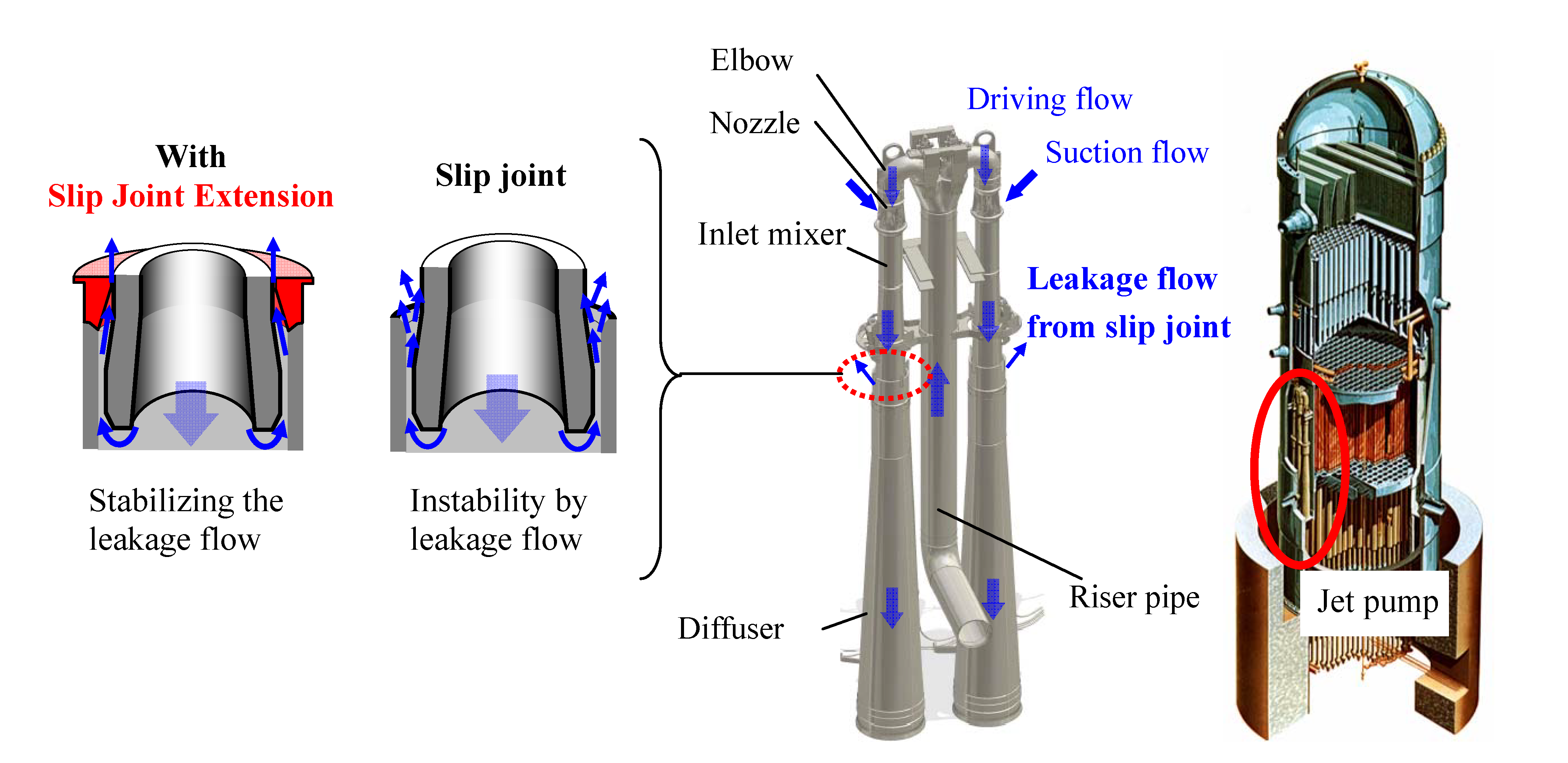
Fig.1 Outline of the jet pump and the concept of the Slip Joint Extension
- (1) Components:
jet pumps in BWR
- (2) Location:
slip joint
- (3) Materials: austenitic stainless steel
- (4) Condition: under water in BWR operating condition
- ・Slip Joint Extension eliminates the root cause of FIV problem of jet pump
- The leakage-flow-induced vibration is one of self-excited vibrations. This phenomenon is
unstable phenomenon which occurs when the slip joint differential pressure exceeds a critical
value [2]. It is well-known that the leakage-flow-induced vibration is easy to occur when the
configuration of gap flow passage is divergent to the leakage flow direction. This is because divergent gap flow passage causes the negative damping [3-6]. In an opposite manner, convergent gap flow passage has the effect to suppress the leakage-flow-induced vibration. The Slip Joint
Extension is designed based on leakage-flow-induced vibration theory to avoid causing the
negative damping. Therefore, it is the solution for eliminating the root cause of the
leakage-flow-induced vibration.
However, the configuration of the gap flow passage of the slip joint is complicated flow passage which consists of convergent, divergent and parallel flow passage region. In addition to this, the leakage flow direction in normal or power uprating condition is opposite in abnormal operating condition such as SLO. Therefore, it is necessary to identify the optimum configuration of gap flow passage of the Slip Joint Extension. Fig. 2 shows the methodology to determine the gap flow passage. At first, the governing equation of fluctuating fluid is derived using the analytical model of 1-D (single-degree-of-freedom) translational system [4]. In the next step, the governing equation should be expressed as transfer matrix form by discretizing the governing equation [7] to apply the actual gap flow passage. Using these transfer matrixes, fluctuating pressure distribution taking along the gap flow passage can be evaluated. Integrating fluctuating pressure gives the equation of fluctuating fluid force eventually. This equation consists of three terms; the first term of acceleration proportional, the second of velocity proportional, and the third of displacement proportional respectively.
The coefficient of the first term represents added mass, the second represents added damping and the third represents added stiffness. As mentioned above, the negative damping causes self-excited vibration. That is to say, leakage-flow-induced vibration is caused when added damping of the second term is negative. Whether the added damping becomes positive or negative depends on the flow condition and the configuration of gap flow passage. Therefore, if we make the inner surface geometry of the Slip Joint Extension so that the added damping should not be negative, the leakage-flow-induced vibration would not be caused. Fig. 3 shows the typical 2 kinds of configurations of the Slip Joint Extensions, which are designed on the basis of dimensions and conditions of jet pumps.
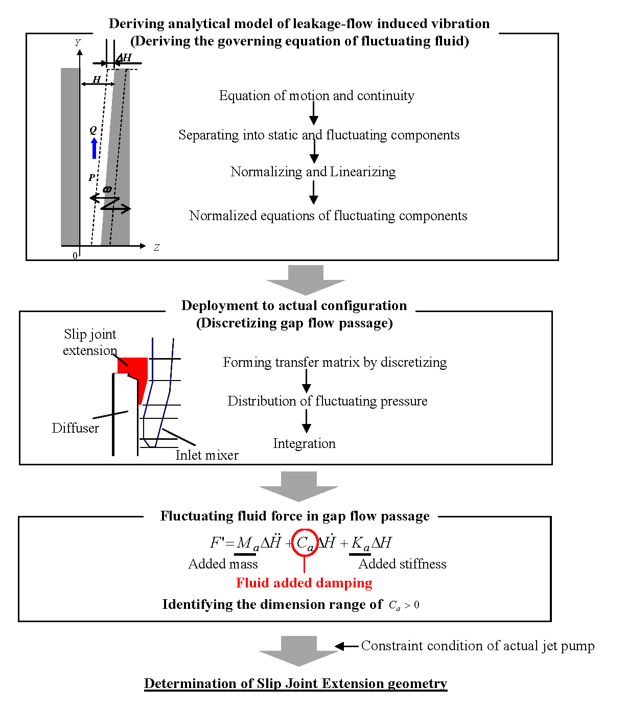
Fig.2 The methodology to determine the gap flow passage of Slip Joint Extension
Fig.3 The determined configurations of Slip Joint Extensions for two typical slip joints in BWR
- ・Slip Joint Extension has effect of suppressing FIV in wide range of operating condition from
particular operating condition like SLO to EPU
- The fundamental tests corresponding to various operating condition were carried out to
confirm the effect of Slip Joint Extensions that were designed by using above methodology. Fig.4
shows the test apparatus. The fundamental test was carried out focusing on the gap flow of the slip
joint. The test facility simulates the slip joint configurations of the typical jet pumps in BWRs. In
this test, the inlet mixer and diffuser were conditioned not to contact each other to cause the
leakage-flow-induced vibration easily.
The test piece, simulating the configuration of the lower end of the inlet mixer tube, was attached to the lower end of the circular cylinder. The upper end of the circular cylinder was welded to a small flange. The test assembly consists of the test piece, the circular cylinder and the small flange. The test piece was inserted to the fixed cylinder simulating the upper end of the jet pump diffuser. Slip joint extension model was installed on the top of the diffuser. The test assembly was fixed on the upper flange of the tank by bolts. Strain gauges were installed on the inside of the upper end of the circular cylinder to measure the vibration response of the test assembly. Before fundamental tests, hammering test was carried out to obtain the conversion factor from strain amplitudes to displacement amplitudes of lower tip end of the test piece.
Flow discharged from the pump goes through the part simulating slip joint, that is, it imitates leakage flow at the slip joint. Flow direction can be adjusted by valves opening/closing. The flow direction from the inside of the diffuser/inlet mixer to the outside (positive flow direction) is assumed in normal operating or power uprating condition. The opposite flow direction (negative flow direction) is assumed in abnormal operating condition such as SLO. The slip joint differential pressure was measured by differential pressure meter. Flow rate was controlled by the valve installed downstream of the pump. The slip joint differential pressure was fully covered the range from negative differential pressure of SLO condition to positive differential pressure of 120% EPU condition. Temperature was not controlled (room temperature of around 20 °C).
Table 1 shows the test cases. There are in total of 8 test cases. Test cases from Case1 to Case 4 are for type A, and Case 5 to Case 8 are for type B. Test cases in upper row in Table 1 are cases without Slip Joint Extension. Test cases in lower row are with Slip Joint Extension. The flow condition of Case1, 2, 5 and 6 is positive flow direction (positive slip joint differential pressure), and Case3, 4, 7, and 8 is negative flow direction (negative slip joint differential pressure).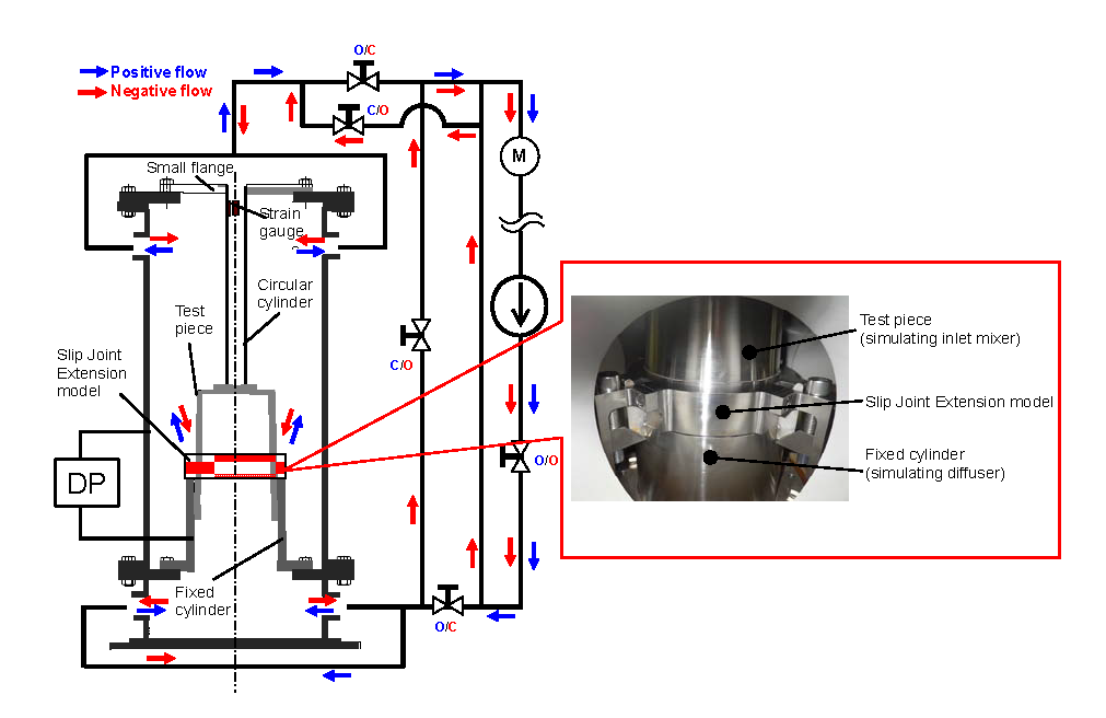
Fig.4 Test apparatus
Table 1 Test cases
Fig.5 shows the relationship between the slip joint differential pressure and displacement amplitudes of Case1 to Case4. The leakage-flow-induced vibration was observed in the condition of negative flow direction without Slip Joint Extension (Case3). It means that the gap flow passage of the slip joint in BWR type A has the risk of leakage-flow-induced vibration in the operating condition like SLO. On the other hand, the vibration was suppressed by installing the Slip Joint Extension (Case4). In the condition of positive flow direction, the leakage-flow-induced vibration was not observed clearly with or without the Slip Joint Extension.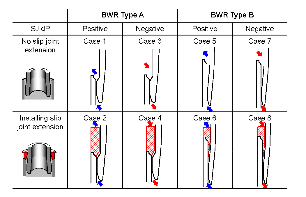
Fig.6 shows the test results of Case5 to Case 8. The leakage-flow-induced vibration was observed in the condition of positive flow direction without the Slip Joint Extension (Case5). It means that the gap flow passage of the slip joint in BWR type B has the risk of leakage-flow-induced vibration in the power uprating condition. However, the vibration was suppressed by installing the Slip Joint Extension (Case6). In the condition of negative flow direction, the leakage-flow-induced vibration was not observed, and the magnitudes of amplitudes were also in the same level with or without the Slip Joint Extension. As shown these test results, it was confirmed that Slip Joint Extension has the effect of suppressing leakage-flow-induced vibration of jet pump in all operating conditions.
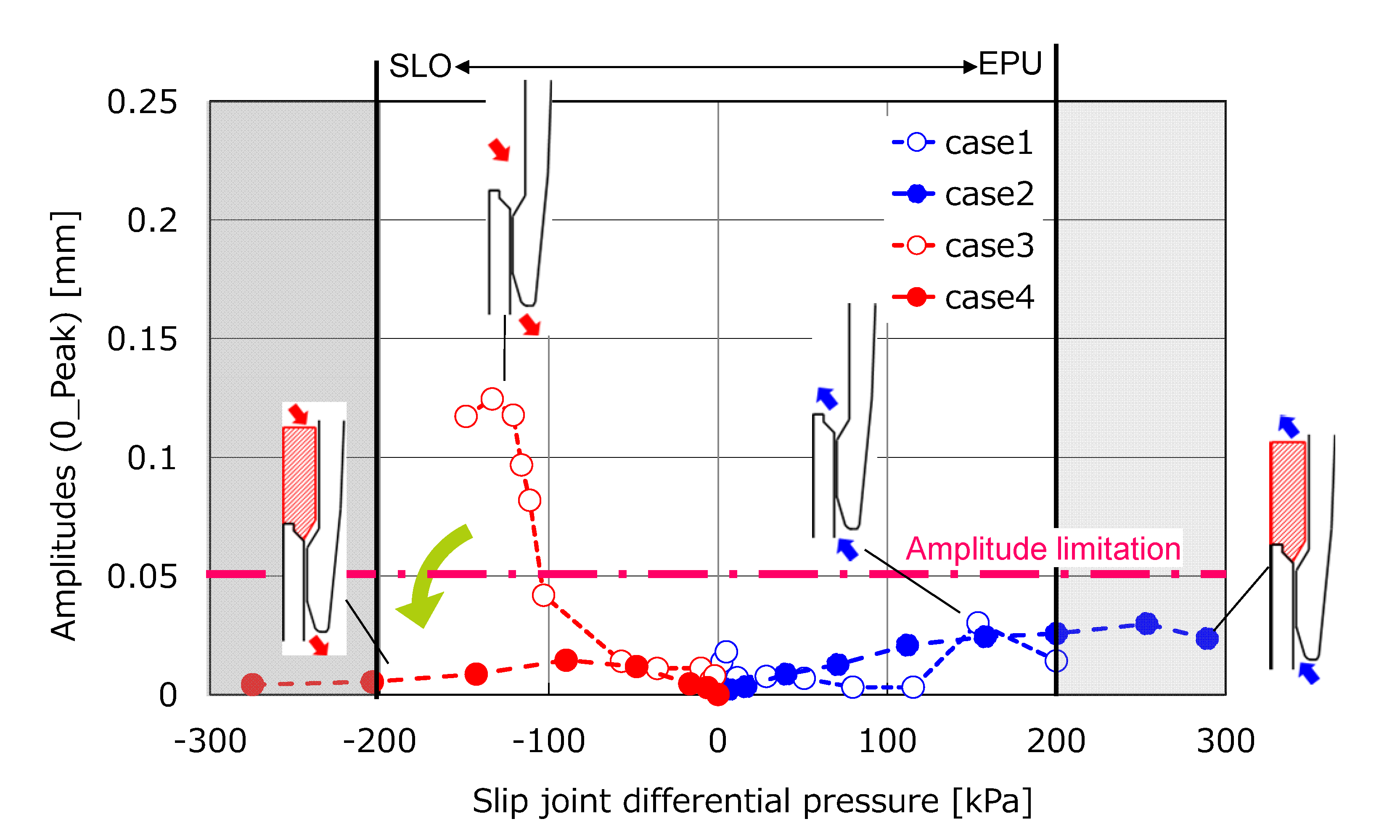
Fig.5 Test results from Case1 to Case4 (Type A)
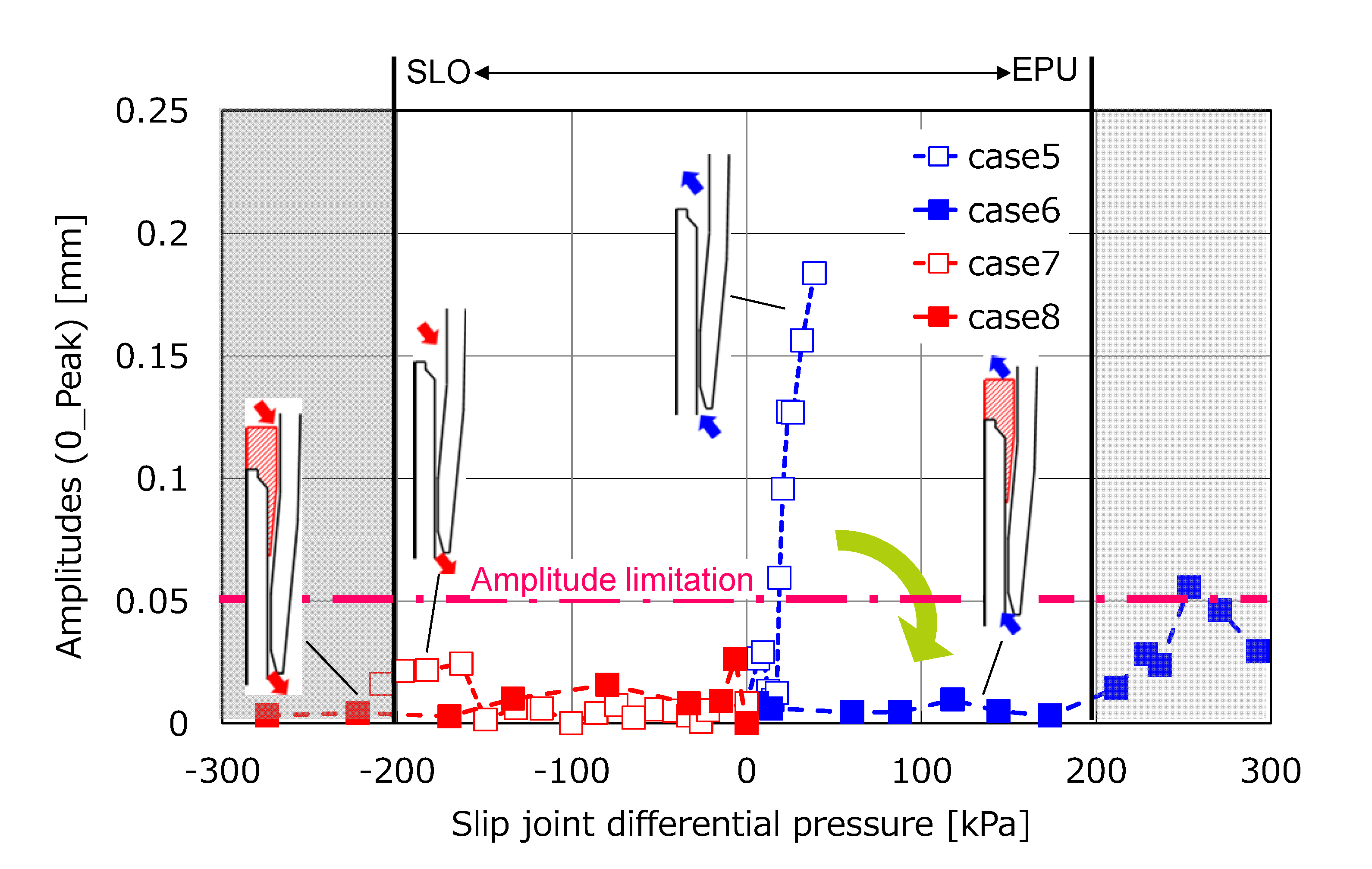
Fig.6 Test results from Case5 to Case8 (Type B)
5. Examples of Application
Slip Joint Extension can be applied to existing jet pumps in BWR without inlet mixers replacement or disassembly. Installation and setting is performed remotely with handling tools, and fixed at the top of diffuser by bolts (Fig.7).
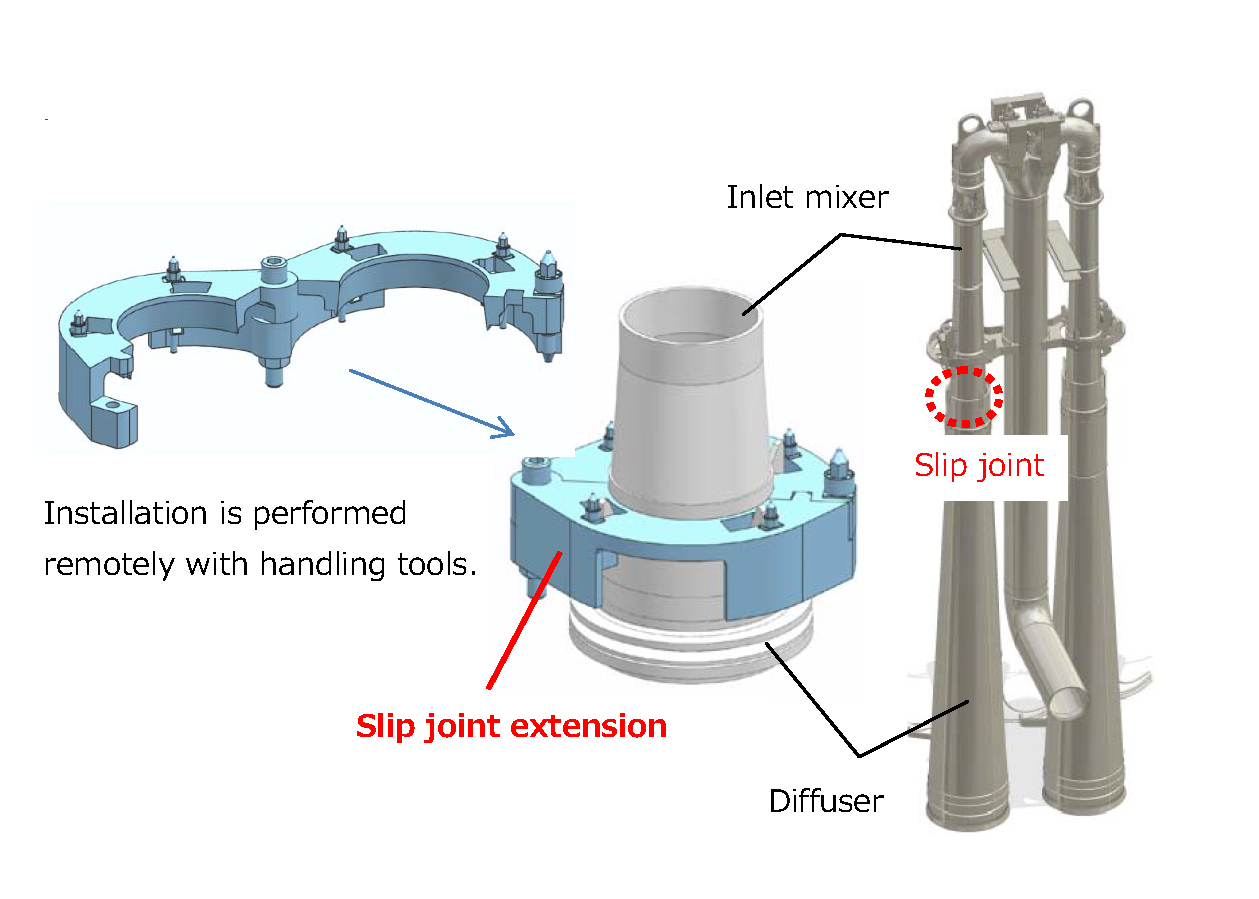
Fig.7 Example of application to jet pump in BWR
6. Reference
- [1]Electric Power Research Institute, August 2012, “Nuclear Sector Rodmaps”, pp.121-123
- [2]T.M.Mulcahy, 1983, “Leakage-Flow-Induced Vibrations of Reactor Componets”, ANL-83-43, Argone National Laboratory
- [3]M.Watanabe, A.Sayano, K.Kinugasa, H.Mori, and T.Hagiwara, 2013, “Improvement of Jet Pump Inlet Mixer in Boiling Water Reactor for Mitigating Flow-Induced Vibration and Fouling”, Proceeding of the ASME 2013 Pressure Vessels and Piping Division Conference, PVP2013-97235.
- [4]F. Inada and S. Hayama, 1987, “A Study on Leakage-Flow-Induced Vibrations (1st Report, Fluid-Dynamic Forces Acting on the Walls of a One-Dimensional, Narrow, Tapered Passage)”, Transactions of the Japan Society of Mechanical Engineers, C, 53(488), pp.933-939 (in Japanese)
- [5]F. Inada and S. Hayama, 1993, “Leakage-Flow-Induced Vibration in a narrow tapered passage (The Effect of Nondimensional Parameters)”, ASIA-PACIFIC VIBRATION CONFFERENCE
- [6]D.E.Li, S.Kaneko, S.Hayama, 1999, “A Study on the Annular Leakage-Flow-Induced Vibrations (1st Report, Stability for Translational and Rotational Single-Degree-of –Freedom Systems)”, Transactions of the Japan Society of Mechanical Engineers, B, 65(635), pp.2251-2256 (in Japanese)
- [7]F. Inada and S. Hayama, 1987, “A Study on Leakage-Flow-Induced Vibrations (2nd Report, Calculation of Fluid-Dynamic Forces Acting on the Walls of a One-Dimensional, Narrow Passage by the Transfer Matrix Method)”, Transactions of the Japan Society of Mechanical Engineers, C, 53(493), pp.1926-1934 (in Japanese)
Japan Society of Maintenology (ejam@jsm.or.jp)