


Classification
1 - A
Array ECT probe called Intelligent ECT Probe (I-Probe) enables high-speed inspection and good detectability at the same time. I-Probe has high detectability to both axial and circumferential defects. It has been applied to full length inspection in Japan since 2003.
A phenomenon in SG secondary side is known that flow slots of Tube Support Plate (TSP) are clogged by scale deposits as shown in Fig.1. Water level oscillation of SG secondary side caused by excessive blockage of scale deposits may become one of the unintended operation troubles. For decreasing blockage, applying countermeasures, such as mechanical cleaning with water jet or advanced scale conditioning agent (ASCA) are performed. Therefore, optimized planning of cleaning timing is important based on monitoring results of blockage condition (blockage ratio *1).
This paper introduces the monitoring method of TSP blockage using I-Probe that has applied for tube integrity. The new method makes it possible not only to inspect tube integrity but also to calculate blockage ratio of every TSP of all tubes and visualize the blockage condition of SG. This new method was applied to some SGs on a trial base and the tendency of blockage ratio is confirmed by comparing the evaluation results to cleaning history.
*1: Although it is difficult to make a uniform definition of “blockage ratio”, the ratio of deposit area within sectional area of flow slot is generally defined as “blockage ratio” in visual monitoring and the same definition is used for this evaluation method.
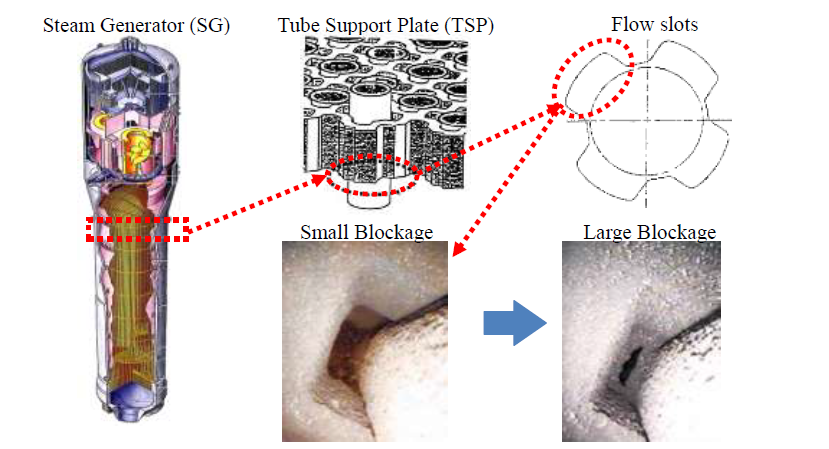
Fig.1 Overview of scale deposits at TSP of SG
- (1) Components: SG
- (2) Location:
TSP of secondary side
- (3) Materials: Alloy 600 and 690
- (4) Condition: In the air
Intelligent ECT probe (I-Probe) is an array probe that is developed for SG tube inspection. Fig.2 shows appearance of I-Probe. It has 24 coil elements (12 coils x 2 lines) circumferentially and can detect both axial and circumferential defects. It enables high-speed inspection which is equivalent to bobbin ECT probe and good detectability which is equivalent to rotating ECT probe. A drive-pickup coil configuration and built-in electronic circuit can enhance signal-to-noise ratio.
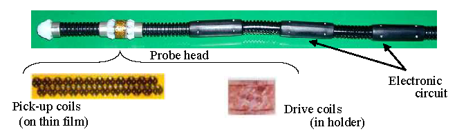
Fig.2 Appearance of Intelligent ECT probe (I-Probe)
Fig.3 shows an example of scale deposit signal with I-Probe at TSP. Color of ECT signal corresponds to signal amplitude of ECT data, and the region of high amplitude is shown redly. As this figure shows, scale deposit signal is strongly appeared at the bottom of TSP.
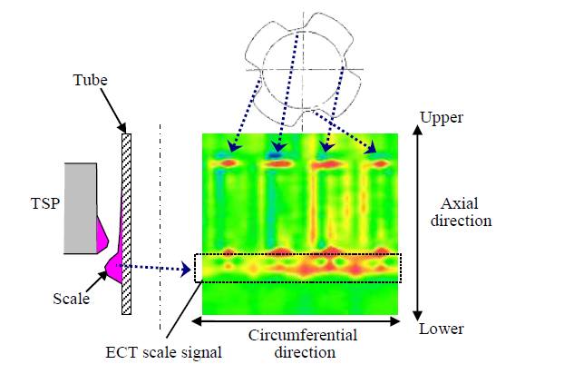
Fig.3 Scale deposits signal of I-Probe at TSP
Fig.4 shows images of visual monitoring of flow slots at TSP and ECT signal corresponding to it. The left example shows the condition that amount of deposit is small and the right example shows the condition that amount of deposit is large. The new blockage evaluation method can evaluate bottom signal considering effect of TSP signal.
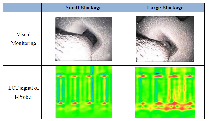
Fig.4 Images of visual monitoring and ECT signal of I-Probe
Fig.5 shows flow diagram of blockage evaluation. Left flow diagram of this figure shows usual periodical inspection for the SG tube integrity with I-Probe. Right flow diagram shows a flow for newly developed blockage evaluation. As acquisition data for the SG tube integrity is also used for blockage evaluation, the blockage evaluation of all TSPs of whole SG can be evaluated without additional data acquisition. Moreover, this process is performed by automatic evaluation software. Therefore, this method has substantial effect on inspection schedule and cost.
Evaluation result of whole SG can be visualized as blockage color map shown in Fig.6. Colored ellipses in Fig.6 show TSPs (from 1st TSP to 7th TSP). Upper left side of the ellipses shows HOT side, and lower right side shows COLD side. As left color bar shows, red color means high blockage ratio and blue color means low blockage ratio. The color map enables visual and intuitive understanding about the overall pattern of blockage distribution, such as a partial increase of deposit.
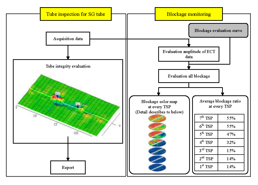
Fig.5 Flow diagram of blockage evaluation
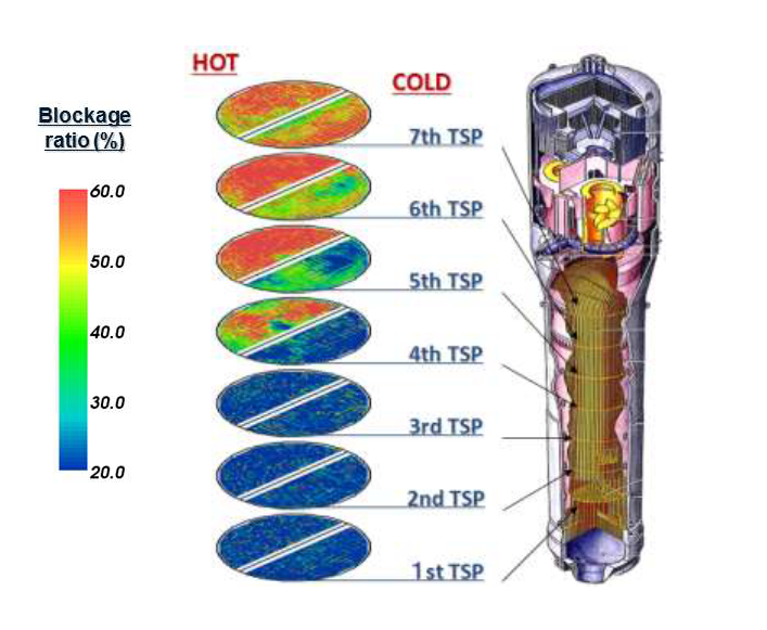
Fig.6 Blockage color map
5. Examples of Application
(1) Blockage evaluation before and after mechanical cleaning
Fig.7 shows blockage color maps before and after mechanical cleaning with water jet. The letter “N” in this figure means outage number. The mechanical cleaning is applied to half area of 3 upper TSPs (from 5th TSP to 7th TSP). Fig.7 (a) shows color map after cleaning at #N, and Fig.7 (b) shows color map after cleaning at #N+1. In Fig.7 (a), it is confirmed that cleaning area and non-cleaning area are clearly distinguished from the difference in the color. The red linear area of upper 3 TSPs shown in Fig.7 (b) corresponds to inaccessible area with water jet of mechanical cleaning.
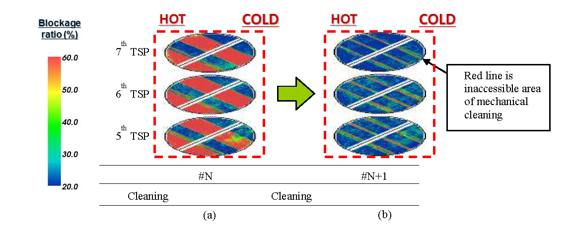
Fig.7 Historical change of blockage color map with mechanical cleaning
(2) Blockage evaluation before and after ASCA
Fig.8 shows blockage color maps in case of ASCA and Fig.9 shows historical change of average blockage ratios that are calculated based on the evaluation results of all TSPs. The letter “N” in this figure means outage number. The cleaning wasn’t applied during the plant operation from “N” to “N+1” and it seems that the blockage ratio of upper TSPs increased, because the red area that means high blockage ratio expanded. On the other hand, it also seems that whole blockage decreased with the ASCA, because the red area decreased gradually after “N+1”. As this figure shows, the historical change of blockage ratio can be visualized on these color maps.
6. Conclusion
The capability of I-Probe to monitor blockage ratio of SG enables optimized planning of SG cleaning and confirmation of the cleaning effects.
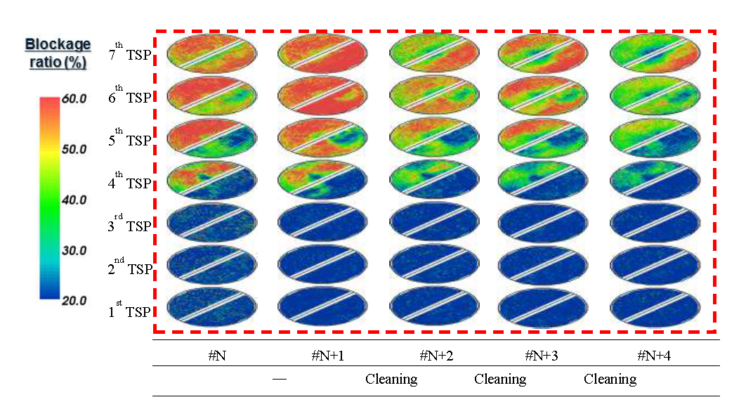
Fig.8 Historical change of blockage color map with ASCA
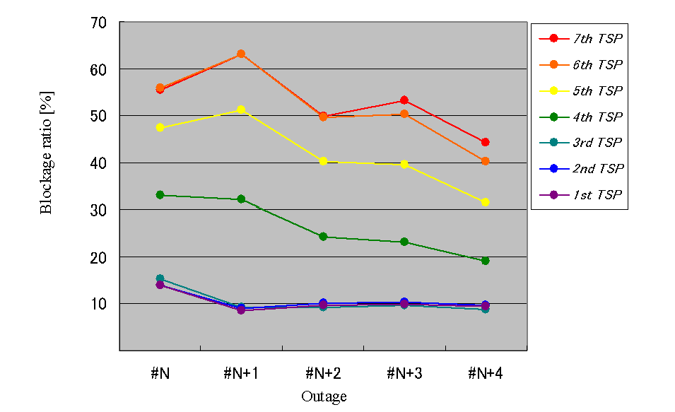
Fig.9 Historical change of blockage ratio with ASCA
7. Reference
- [1]J. Siegel, M. Takatsugu, et al., “The Value of The MHI Intelligent Array System for SG Inspection”, Proceedings of the 9th International Conference on NDE in Relation to Structure Integrity for Nuclear and Pressured Components, Seattle, 2012, pp.352-359
Japan Society of Maintenology (ejam@jsm.or.jp)