


Vol.4, No.3, NT49
Advanced INLAY System for Reactor Vessel of PWR
Mitsubishi Heavy Industries, Ltd. (MHI)
KEYWORDS:
INLAY, Cylindrical Container, PWSCC, Alloy 600/690, Reactor Vessel, Manipulator
1. Technical summary
Classification
5 - A(Improvement)
- (1)In recent years, Primary Water Stress Corrosion Cracking (PWSCC) has been detected at the safe-end with Alloy 600 during the inspection of the RV nozzles of PWR. To prevent PWSCC, stress or material improvement methods have been applied in Japan. Material improvement by replacing the material from Alloy 600 to Alloy 690, which has high resistance against PWSCC, is a fundamental countermeasure, and applications for this technology continue to grow.
- (2)Both conventional and advanced INLAY systems have been developed for activities inside nozzles as preventive maintenance against the PWSCC of RV outlet/inlet nozzles, and they are also used for repair work when a PWSCC is detected.
- (3)During outages, the cavity is filled with water to avoid exposure from highly activated core internals. The cylindrical container is installed in the cavity to secure an atmospheric working space inside the nozzles (Fig. 1).
- (4)First, we perform circumferential machining to remove the Alloy 600 from inside the nozzle. Then we perform circumferential welding with Alloy 690, as well as surface finishing by machining and buffing and examinations (Fig. 1).

Fig. 1 INLAY method using the cylindrical container for RV and main procedures as preventive maintenance
- (5)We also developed an advanced INLAY System to shorten the work periods and reduce radiation exposure. Our newly equipped manipulators can handle small tip devices, so a maximum of four nozzles work for a 4-loop plant, and three nozzles work for a 3-loop plant; these can be performed in parallel. As a result of remote installation, workers do not need to enter the high-dose nozzles for installation (Figs. 2 and 3).
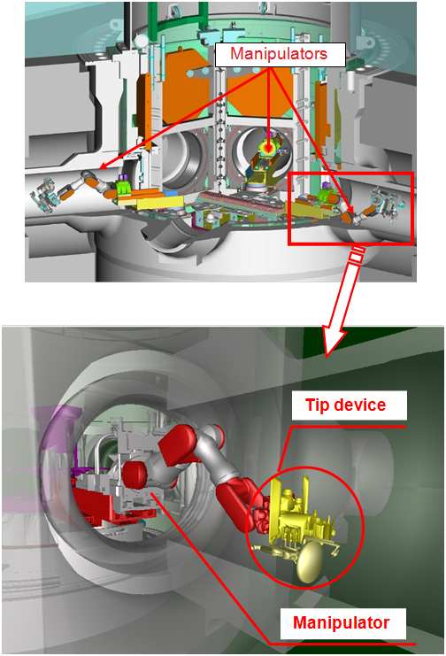
Fig. 2 Advanced INLAY devices (Manipulators and tip devices)
Fig. 3 Animation of Advanced INLAY method
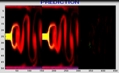
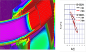
- (6)Machining can be accurately done based on the as-built shape of the nozzle. The shape of the weld’s configuration inside the nozzle is not ideal, since the nozzles were deformed due to joint welding in the construction. Furthermore, the weld’s surface was not finished by machining but by manual grinding. We developed laser tracing and calculation systems of the trajectory of the bite for high-accuracy machining (Figs. 4 and 5).
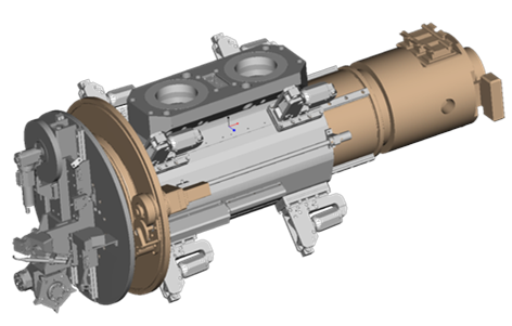
Fig. 4 Machining device
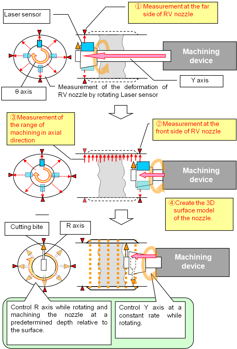
Fig. 5 Laser tracing system and calculation system
- (7)We also considered the risk of detecting the PWSCC defects after machining before welding. If PWSCCs are detected, they are removed to avoid any further risks. The advanced INLAY system can be applied up to half thickness of the nozzle. After machining to remove defects, we repair them by structural welding. Then we circumferentially machine and weld with Alloy 690 as preventive maintenance (Fig. 6).
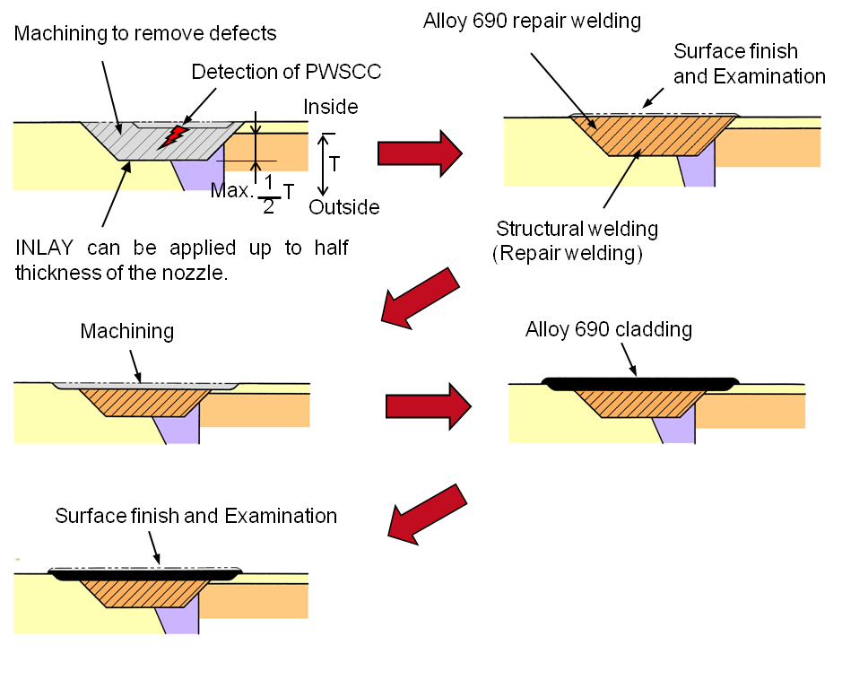
Fig. 6 Procedures as repair work when PWSCC defects are detected
2. Level of development/application
Phase 3 : Publicly accepted phase
3. Scope
- (1) Components: Reactor Vessel (RV) of PWR.
- (2) Location: Inside of dissimilar welds of outlet / inlet nozzle of RV concerned in PWSCC
- (3) Material: Alloy 600 (Nickel based alloy)
- (4) Condition: This method can be applied underwater with isolated air chamber system called cylindrical container.
4. Features
- (1)Since we can perform the work with a maximum of four nozzles in parallel, advanced INLAY work can be completed in a relatively short period. With the conventional INLAY system, the work period takes 51 days for four nozzles. However, the advanced INLAY system only requires 30 days.
- (2)Since advanced INLAY devices can be installed and operated remotely, radiation exposure is reduced. Using the advanced INLAY system, the radiation exposure was one-third compared with the conventional INLAY system.
- (3)We applied the ambient temperature, temper bead welding technique.
- (4)Our advanced INLAY system can be applied as repair work if PWSCC defects are detected.
5. Examples of Application
The advanced INLAY system was applied to three Japanese plants from July 2010 to March 2012.
6. Reference
- [1]THE KANSAI ELECTRIC POWER CO., INC. (KEPCO) and MITSUBISHI HEAVY INDUSTRIES, LTD. (MHI); “INLAY Method Using the Cylindrical Container for Reactor Vessel of PWR,” Vol. 2, No1, May 2010
http://www.jsm.or.jp/ejam/Vol.2.No.1/NT/19/article.html - [2]K. Yamamoto, N. Sugimoto, K. Onishi, K. Okimura, Mitsubishi Heavy Industries (MHI) ; IAEA-CN-194-080 “PWSCC Preventive Maintenance Activities for Alloy 600 in Japanese PWR Plants” 3rd International Conference on NPP Life Management (PLIM) for Long Term Operations (LTO) May 14-18, 2012
- [3]K. Onishi and Y. Kobayashi, Mitsubishi Heavy Industries (MHI); “Advanced INLAY System for Inlet/Outlet Nozzles of RV for Preventive Maintenance Against Alloy 600 PWSCC in Japanese PWR Plants” EPRI INTERNATIONAL BOILING WATER REACTOR AND PRESSURIZED WATER REACTOR MATERIALS RELIABILITY CONFERENCE AND EXHIBITION July 16–19, 2012
7. Contact
Japan Society of Maintenology (ejam@jsm.or.jp)