


Classification
1 - A (Non-destruction examination of metallographic structure)
When a crack is detected in nuclear reactor core internals, the details need to be carefully surveyed. In order to survey the core internals simply, we developed new microscopic observation techniques. These techniques were “Gel Electrode” (Fig. 1) and “Underwater Microscope” (Fig.2 (a)).
A gel electrode consists of porous material, cathode, anode, and a power source. Etching solution is contained in the porous material in the gel. To electrify a direct current between anode and cathode, the surface of core internals is etched when the core internals are touched with anode and cathode. After electrolytic etching, the fusion boundary and grain boundary can be seen. Because of high-deformation performance, gel electrode can be used on a curved surface such as a CRD housing weld zone.
The underwater microscope consists of a CCD camera, focus lens, zoom lens, and watertight container. Using the microscope enables us to see surface figures of nuclear reactor core internals directly without taking boat samples or replicas that transcribe the surface shape. An example of observation using specimen is shown in Fig.2 (b).
Using these methods significantly reduces the labor needed to complete a microscopic observation.
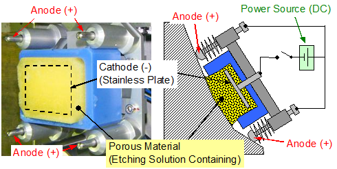
Fig. 1 Schematic of Gel Electrode
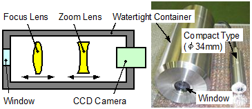
Fig. 2 (a) Schematic of Underwater Microscope
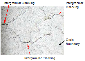
Fig. 2 (b) Grain Boundary and Intergranular Cracking
(Underwater Microscope was applied)
Phase 2 : Industrial Confirmation Phase
- A gel electrode was used in a nuclear power plant for the first time in 2009.
(1) Gel electrode can be used in electrolytic etching.
(2) After electrolytic etching, fusion boundary and grain boundary can be seen.
(3) Gel electrode can be used on a curved surface shape.
(4) After electrolytic etching, an underwater microscope was used to investigate the crack. We saw the fusion and the grain boundary as well as stress corrosion cracking without the need to take boat samples or replicas that transcribe the surface shape.
(5) Using these methods significantly reduces the labor of the observation.
(6) Underwater Microscope has the capacity to shoot pictures at 768 x 494 pixels resolution.
Supplementary explanation
Visibility after electrolytic etching (laboratory test)
We confirmed that the fusion and grain boundary were visible after applying the gel electrode to the weld zone. A schematic of the specimen is shown in Fig.3. The specimen was an alloy 600 plate welded by alloy 182 and alloy 82. The electrolytic etching area was a polished area. The specimen after electrolytic etching is shown in Fig.4. Boundaries (Alloy 600 and Alloy 182 or 82) and Fusion Boundary (Alloy 182 and Alloy 82) could be seen in the electrolytic etching area. A close-up of the near fusion boundary is shown in Fig. 5. Grain boundaries and fusion boundary could be seen after electrolytic etching.
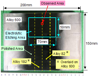
Fig. 3 Schematic of Specimen
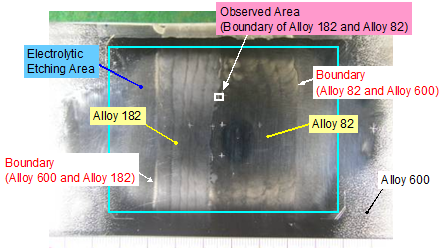
Fig. 4 Specimen after Electrolytic Etching (Gel Electrode was applied)
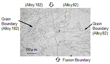
Fig. 5 Grain Boundary after Electrolytic Etching (Gel Electrode was applied)
Core Shroud Support Cylinder on Tokai No. 2 Power Station in 2009 [1]
We applied gel electrode to the core shroud support cylinder on Tokai No. 2 power station in 2009. A schematic of core shroud support cylinder is shown in Fig. 6. Example of crack detected near V8 vertical weld line is shown in Fig. 7. However, the fusion boundary between base and weld metal could not be found near the crack, because the surface of core shroud support cylinder was covered with a film of oxide.
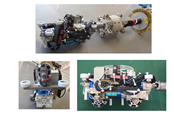
In order to find the V8 vertical weld line, we applied a gel electrode to the core shroud support cylinder after polishing the surface near the crack. Gel electrode was applied by using a remote access apparatus. The schematic of a remote access apparatus is shown in Fig. 8. A remote access apparatus was installed with CRD housing and mounted on a core support plate. The electrode was swung and touched with the inner surface of a core shroud support cylinder. A schematic of electrolytic etching is shown in Fig. 9. The electrode was touched with a polished area of the core shroud support cylinder.
The surface of the core shroud support cylinder after the gel electrode was applied is shown in Fig. 10. The fusion boundary could be clearly seen and the V8 vertical weld line was identified.
We found that the crack was located in the V8 vertical weld line.
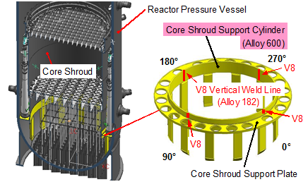
Fig. 6 Schematic of Core Shroud Support Cylinder on Tokai No. 2 Power Station
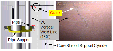
Fig. 7 Example of Crack (Near V8 Vertical Weld Line) on Tokai No. 2 Power Station
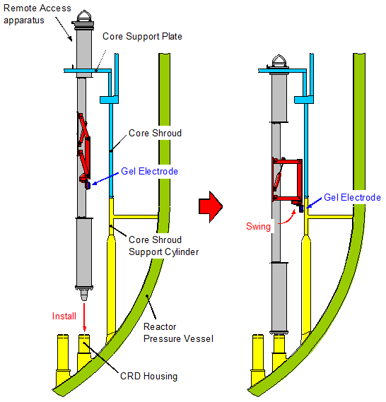
Fig. 8 Schematic of Remote Access Apparatus for Gel Electrode
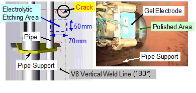
Fig. 9 Schematic of Electrolytic Etching (Near V8 Vertical Weld Line)
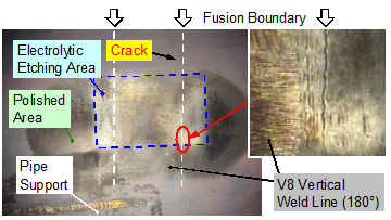
Fig. 10 Fusion Boundary after Electrolytic Etching (V8 Vertical Weld Line)
[1]The Japan Atomic Power Company, Press release (2009). (http://www.japc.co.jp/news/bn/h21/211208.pdf)
Japan Society of Maintenology (ejam@jsm.or.jp)