


Hitachi-GE Nuclear Energy, Ltd.
Hitachi, Ltd.
Vol.10, No.3, NT91
Development of a MAV Equipped with Rotatable Attachment Mechanism for Movable Observation System
KEYWORDS:
Visual inspection, MAV, Confined and indoor enviroment
1. Technical summary
Classification
6 - C
Recently, infrastructure inspection services utilizing Micro-Aerial Vehicles (MAV) have started being offered, and are being used widely in industrial fields. MAVs are attracting much attention, particularly as an inspection solution in environments where it is difficult to cover the entire area using crawlers and other robots that travel on the ground, or for high locations where a scaffold or other apparatus would be needed for a human inspector. On the other hand, there are limitations to their application in indoor or confined environments for example the buildings in Nuclear Power Station (NPS), such as the risk of contact with surrounding objects and inability to use GPS.
Currently, many MAVs called multi-rotor helicopters are being developed, which use multiple propellers to control their attitude [1][2]. Other designs are also being developed, such as one with two counter-rotating propellers combined with attitude control flaps [3], one with a rotating spherical shell to mitigate interference from obstacles [4], and a multi-coptor that uses magnets to attach to steel structures, reducing power consumption [5].
The authors have developed a MAV equipped with a spherical exterior shell (frame structure) that allows contact with its surroundings, and reduced in size from 0.7 m to 0.5 m for inspection in interior and confined spaces [6]. The objective of this MAV is to increase efficiency of inspection work in confined environments and in high locations where temporary scaffolding would otherwise be needed. It is used to conduct primary screening inspections before visual inspection by a human inspector.
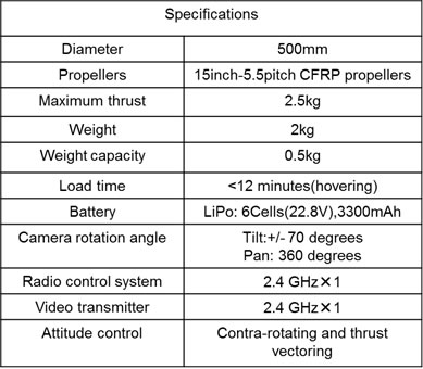
This article reports on design of an MAV with an additional mechanism to attach to metal structures such as H-beams, reducing power consumption and increasing operating time. A prototype of the MAV is shown in Fig. 1, and specifications are given in Table 1. Testing with the prototype confirmed that it is able to attach to and detach from the ceiling and to check the surroundings while attached. We also verify the ability to capture wide-area video, and conduct inspections using it as a mobile inspection camera, compensating for blind-spots in other work.
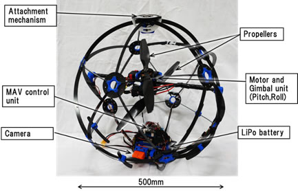
Figure 1 Photograph of the MAV
Table 1 Specification of the MAV
2. Development Phase
3. Scope
- (1) Components:
Plant, A disaster plant such as Fukushima Daiichi Nuclear Power Station, equipment, remote control equipment
- (2) Location:
Confined and indoor enviroments, high locations
- (3) Materials:
N/A
- (4) Condition:
N/A
4. Features
(1) Spherical shell and self-righting structure and thrust vectoring counter-rotating flight mechanism
Since thrust is proportional to the cube of the propeller diameter, it is desirable to use as large a propeller as possible. To use the cross sectional area of the aircraft effectively, we used two counter-rotating propellers for thrust, with a mechanism controlling pitch and roll of the propellers to control attitude. For yaw control, the rates of rotation of the upper and lower propellers are adjusted, controlling the total torque from the counter-rotating propellers.
A spherical shell (frame structure) is provided to prevent contact between the propellers and surrounding objects. The shell is an icosahedral truss structure approximating a sphere, strong enough to prevent contact with objects in any direction. The shell is made by CFRP. Also, since the center of gravity is positioned below the center of the sphere, it acts as a self-righting mechanism which can return the vehicle to an upright position from which it can take flight again, regardless of its attitude when landing.
(2) Yaw-controllable ceiling attachable camera system
Hovering continuously while conducting inspections consumes a large amount of power, so we studied use of magnets to attach to metal structures within the plant or building being inspected. Power to the propellers is cut while attached, to increase working time of the device.
The circular plate attached to the magnet can be rotated in the yaw direction, and the apparatus can attach and detach from the ceiling by raising or lowering a detachment ring surrounding the plate. The detachment ring is lowered to attach to the ceiling, exposing the magnet (Figure 2), and to release, the detachment ring pushes against the ceiling, removing the magnet from the structure.
The round plate attached to the magnets can rotate freely, so the entire MAV can rotate in the yaw direction around the center of attachment. This allows the yaw direction of the camera to be set anywhere in a 360 degree range. This is controlled by adjusting the torque from the two counter-rotating propellers. The pitch direction of the camera can also move in a +/- 70 degree range, allowing images over a wide range to be checked.
We conducted tests to check the field of view, as shown in Figure 3. The MAV attached to a steel cross beam, and we checked the field of view of the onboard camera using markers placed on the ceiling, a wall beside the MAV, the floor, and on a desk. By changing the direction of the MAV and the camera tilt angle, the numbered markers could be read as shown in the figure.
Next, as an example demonstrating the mobile fixed-point camera, we studied us of the MAV as a camera to compensate for blind spots when operating an industrial robot remotely. The remotely controlled robot arm was arranged as shown in Figure 4, while watching video from a networked camera placed near the robot arm. However, the robot arm itself, as well as work items sometimes obstructed the view, so it was difficult to see the end of the robot arm at all times. As such, we used the MAV reported here to verify that it can be used as a mobile supporting camera to compensate for blind spots. The MAV itself was radio controlled, and the video from the onboard camera was also obtained wirelessly.
In the experiments, the MAV attached to the H-beam on the ceiling opposite the robot arm, and by filming the robot arm, a good view of the end of the arm was possible during work as shown in Figure 5. This promises to enable even more accurate remote control of the robot arm (refer to attached video).
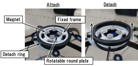
Figure2 Schematic diagram of attachment mechanism
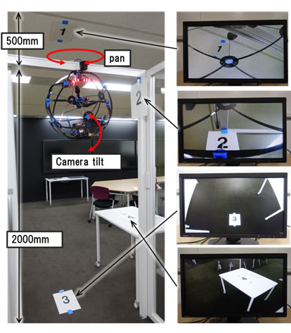
Figure3 Camera angle experiment
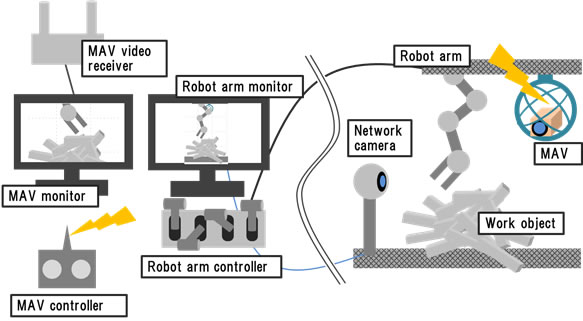
Figure 4 Robot arm and MAV control systems

Figure 5 Images of the arm* tip while working
*This arm (Muscular Robot) was developed by the subsidized project from the Ministry of Economy, Trade and Industry; the project has been undertaken by Hitachi-GE Nuclear Energy, Ltd. as a member of the International Research Institute for Nuclear Decommissioning.
video aprox. 1min.
5. Example of Application
- We prototyped an MAV with a spherical outer shell allowing contact with surrounding objects, a self-righting structure, a vector-thrust dual-counter-rotating flight mechanism, and an attachment/detachment mechanism using magnets, and confirmed that it was able to attach and detach from steel structures.
- We demonstrated an application to support remote operation of a robot arm. The MAV was placed in the blind spot of the networked camera, showing that a good view of the end of the robot arm could be obtained.
6. Reference
- 1.S. Shen, N. Michael, and V. Kumar, “Vision-Based Autonomous Navigation in Complex Environments with a Quadrotor,” in IEEE International Conference on Intelligent Robots and Systems, Tokyo, Japan, 2013.
- 2.Koji Kawasaki, “MUWA: Multi-field Universal Wheel for Air-land Vehicle with Quad Variable-pitch Propellers,” IROS 2013 in Japan
- 3.L. Daler, A. Klaptocz, A. Briod, M. Sitti and D. Floreano. “A Perching Mechanism for Flying Robots Using a Fibre-Based Adhesive,” ICRA 13, Karlsruhe, 2013.
- 4.S. Mizutani, Y. Okada, C. J. Salaan, T. Ishii, K. Ohno and S. Tadokoro: “Proposal and Experimental Validation of a Design Strategy for a UAV with a Passive Rotating Spherical Shell,” Proc. of the 2015 IEEE/RSJ International Conference on Intelligent Robots and Systems, 2015.
- 5.Kazuaki Yanagimura, Kazunori Ohno,Yusuke Totsuka,Satoshi Tadokoro, “Research and Development of an Adsorption Mechanism Using Magnets for Quadrotors,” The Robotics and Mechatronics Conference 2013 in Tsukuba
- 6.Azusa Amino, Yukio Yamamoto, “Development of a Thrust Vectoring and Contra-Rotating Propeller MAV Equipped with Outer Shell,” The Robotics and Mechatronics Conference 2015 in Kyoto
7. Contact
Japan Society of Maintenology (ejam@jsm.or.jp)