


Classification
1 - C
The reliability of inspection results is affected by the skill of examination personnel. This is especially true for manual ultrasonic testing (UT). In Japan, UT for in-service inspection (ISI) has been performed by highly experienced UT engineers. However, many Japanese nuclear power plants (NPP) have ceased operation, and periodic ISI is not performed regularly. In contrast, performance demonstration systems such as PDI programs are currently only being applied to crack depth sizing and Weld Overlay (WOL) inspection, rather than crack detection in Japan. This is based on a national research project that reports that good inspection results and reliability are achieved with general examination procedures and "highly skilled" UT engineers. In addition, Japanese inspection companies have been operating their own training programs. For these reasons, a highly efficient, highly effective training program is required for high reliability UT examination.
However, this training program needs to use test specimens, which should be fabricated by the same process as used on parts of actual plants, and have realistic defects. The number and design of test specimens are among the most important points to be considered during training or assessing the qualification of UT examination personnel (Figure 1). But these realistic test specimens are very expensive and take much time to fabricate. If the number of test specimens is not enough, trainees can predict the defect locations and characteristics, it will cause a decrease the training effect. In addition, higher training effect can be achieved by guidance including feedback of the trainees own scan result.
On the other hand, since the simulation system has the advantage of generating and editing many ultrasonic wave data, a simulated UT system using a computer mouse or touch sensor was proposed for training. However, this system proved to be inadequate as a replacement for actual UT work. In this study, we developed a novel virtual UT system that accurately simulates UT work for piping welds.
Figure 2 shows the basic system design for the virtual UT system. The master sensor of the 3D position system is set on the dummy pipe, and a UT engineer moves the dummy UT probe, which includes a slave sensor. The 3D position system detects the position and skew angle of the dummy probe. This system should detect the absolute position and skew angle of a dummy probe through a "real-time response." In order to simulate realistic flaw detection, the dummy probe should have no wires or special equipment requiring cables. We examined various position detection systems, including CCD cameras, pressure sensors, touch sensors, and lasers. Ultimately, a 3D electromagnetic position detection system was selected. This system can detect sensor positions and angles with a high degree of accuracy and real-time response. It also possesses a slave sensor that is as small as a UT probe. Therefore, the system can calculate the slave sensor when it is in contact with the piping surface using the 3D position detection system. The PC contains a large on-board memory that is necessary for the storage of large data files in the size waveform. Additionally, we choose an iPad as a sub-monitor to reduce the number of wires required for connecting a PC to a sub-monitor.
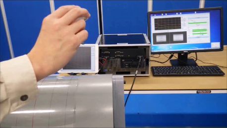
Figure 3 shows the overview of the virtual UT system. The 3D position and skew angle of the dummy probe are sent to a control PC via a USB port. When one starts up the software and loads the waveform data, they move to the on-board memory of the PC. The control PC displays the waveform depending on the dummy probe position, angle, and contact with the dummy pipe. The same waveform is displayed on the sub-monitor (dummy UT instrument). The software has a multi-language function (Japanese and English, along with other to-be-determined languages). Our in-house system has three sizes of dummy pipe diameter: large (600 mm), middle (350 mm), and small (150 mm). In addition, this system can record a scanning log as in figure 4. The system records the probe position and skew angle every 0.1 seconds, this function is very useful for training and analysis. The video (Video.1) shows the operating of this virtual UT system.
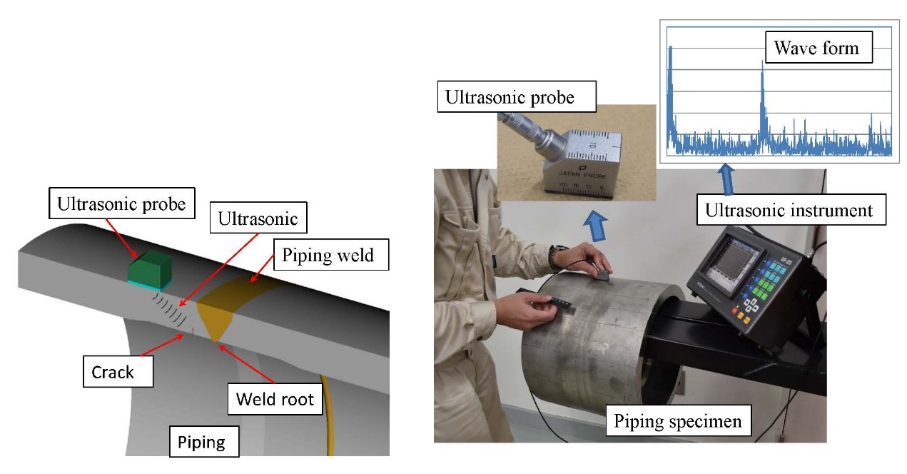
Fig. 1 A crack detection training using actual test specimen and instrument
When training examination engineers using actual test specimens that include artificial flaws, it is necessary to prepare a large number of test specimens. In the case of a small number of test specimens, a trainee will know the position and number of cracks on the test specimen, which in turn will reduce the effectiveness of training.
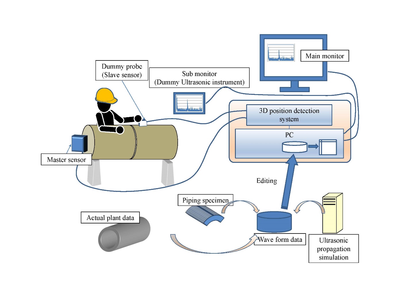
Fig.2 System drawings of virtual UT system
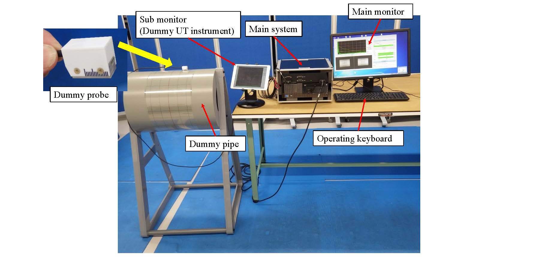
Fig.3 Overview of the virtual UT system
This system is designed with transportability, i.e. it can be transported easily.
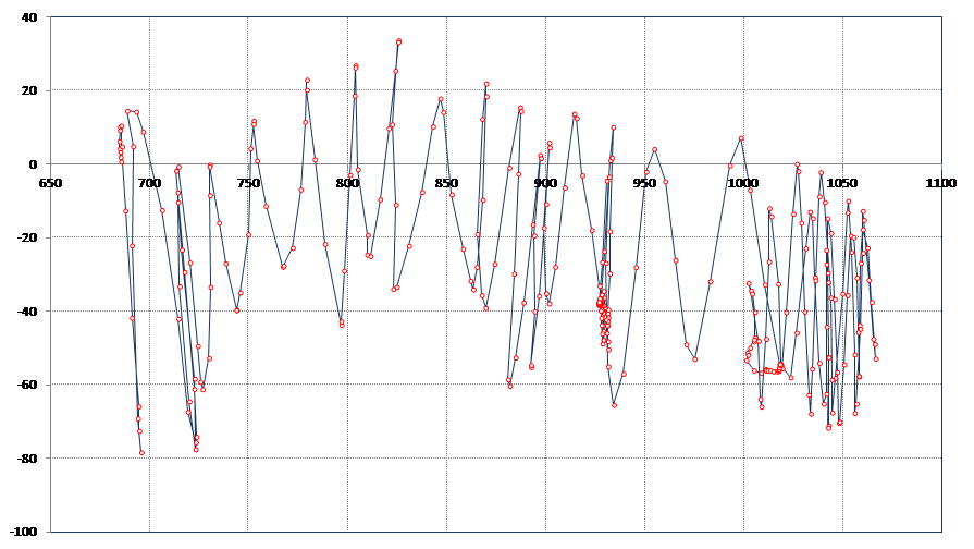
Fig.4 Sample of the scanning log result
This system can record a scanning log. This function is very useful for training and analysis.
Video 1 Virtual UT system
- (1) Components:
Piping and vessel welds
- (2) Location:
Weld joints
- (3) Materials:
Ferritic and austenitic
- (4) Condition:
N/A
- This system completely simulates the crack detection process using actual specimens.
- There is no need to fabricate many test specimens.
- A large number of flaw detection exercises are possible by editing data.
- Many examination engineers can experience the crack detection that would occur in the case of actual plant damage.
5. Example of Application
- TRIAL TRAINING
We performed a trial training to confirm the effectiveness of training prospective engineers with the virtual UT examination system. The trainees comprised three groups: ISI-UT engineers ("high skill"), UT engineers without any ISI experience ("just certified" UT engineer), and non-UT engineers ("Not certified" engineer). In this training, the highly skilled UT engineers had had previous experience in performing UT for stainless steel piping inspections during ISI. UT engineers without ISI experience have usually performed UT; however, most of them use a straight beam technique or measure the thickness. The non-UT engineers work for an inspection company but usually perform liquid penetrant testing or visual testing rather than UT.
They all received general usage instructions, pre-examinations, hands-on practice, a post-training examination, and a questionnaire. During the hands-on practice, some trainees used virtual UT systems and received feedback during the pre-examination, while others were trained using actual small specimens and actual cracks (as would be done by conventional training schemes). The grading of the examinations was calculated as per the following equation. This equation is set to be approximately 100 points when perfect answer, and these coefficients are set with reference to acceptance criteria of ASME B&PV code section XI appendix VIII.
[Score] =
[correct crack detection] × 6 + [correct rejection of unflawed areas] × 7− [missed detections] × 16 − [false calls] × 14 − [over time] × 1+ 50
Figure 5(a) shows the pre-examination results obtained by each group (POD = probability of detection, FCR = false call rate). This figure shows that the highly skilled UT engineers could detect cracks with very few false calls. The just-certified group detected most of the cracks but also made many false calls. This means that the difference between the highly skilled and just-certified groups was that the highly skilled ones could eliminate gray zone signals.
Figure 5(b) shows the effectiveness of the training that was done with the virtual UT examination system and the actual small test specimen. This result shows that the effectiveness of the virtual UT system training was higher than that of actual UT training done using a limited number of small specimens. The important thing to note is that if UT training is performed with actual materials, it is not possible to provide feedback on the correct answer to the candidate. However, with virtual UT training, many UT data sets can be generated and edited. This allows the correct answer to be used to provide feedback (FB) and instruct the trainees in the correct measurement process.
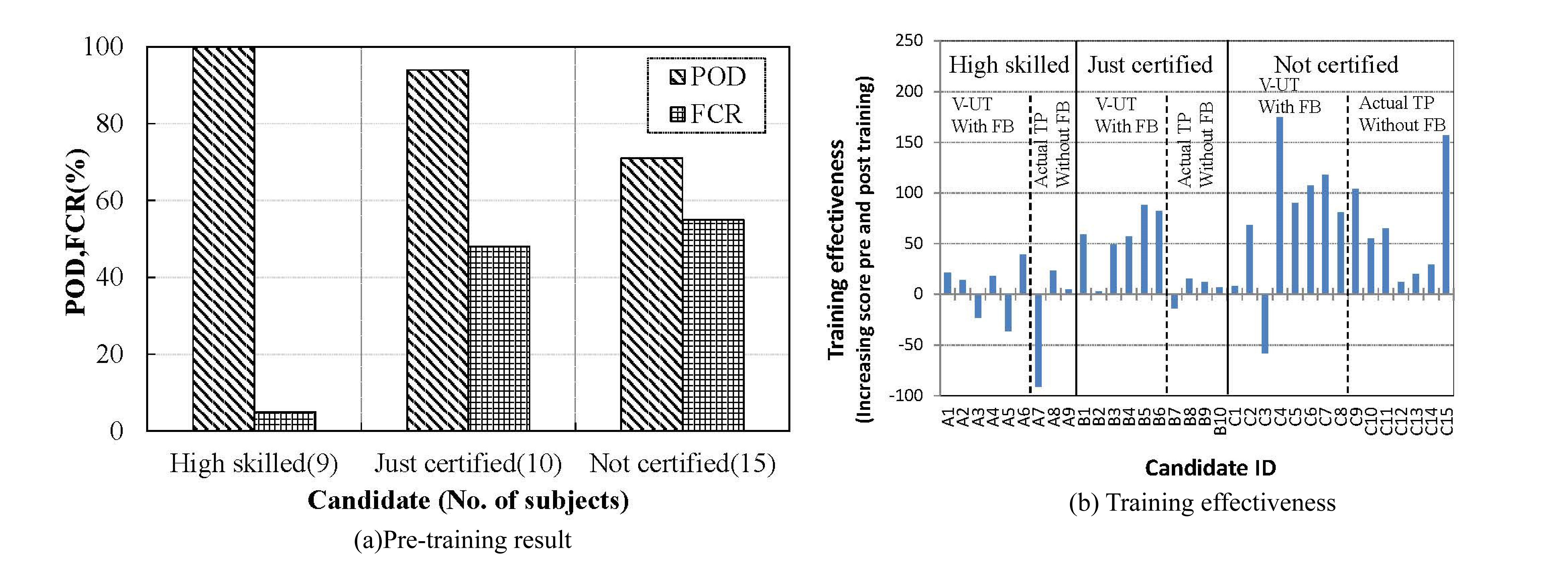
Fig.5 Application result of virtual UT system
Figure (a) shows that the highly skilled UT engineers and just-certified group detected most of the crack signals. The difference between the highly skilled and just-certified groups was the false call ratio. Figure (b) shows that the training effectiveness using the virtual UT system (V-UT) is better than the training using a small actual sample because feedback (FB) process can be applied to the training when using V-UT.
We have developed the virtual UT examination system and estimated the effectiveness of using it during training of UT engineers. In this trial training, the UT engineers said the training using this system was very good, effective and good simulate actual UT examination, and the results show that the virtual system is better at training UT engineers than UT training using actual samples without feedback. Additionally, the difference between a "high skilled" UT engineer and UT engineer with no ISI experience is that the "high skilled" engineer is better able to eliminate unflawed signals, although most engineers with no ISI experience can detect the crack signal.
Following on from this, we have already begun studying a highly efficient training program using a virtual system and the human factor of the UT examination results.
6. Reference
- 1.H. Shohji, K. Hide, Development of Prototype Virtual Testing System for Ultrasonic Examination Engineers, CRIEPI Research report, Q14007(2015).
- 2.H. Shohji, A Study on Skill Improvement of Examination Personnel using a Virtual Ultrasonic Testing System, CRIEPI Research report, Q16012 (2017).
- 3.H. Shohji, K. Hide, “Development of Virtual Ultrasonic Testing System,” Proceedings of 11th International Conference on NDE in Relation to Structural Integrity for Nuclear and Pressurized Components, WE_1_A-4 (2015).
Japan Society of Maintenology (ejam@jsm.or.jp)