


Classification
1 - A
Electro-Magnetic Induction Testing method (EMIT) is widely used in the industries. However, due to the deterioration of sensitivity by increase of Lift-Off (distance between sensor and test piece) and the limitation of penetration of magnetic flux into thick magnetic and conductive material such as carbon steel, its application is limited to comparative testing between sound and defective samples. The newly developed “i Eddy” system enables the measurement of wall thickness and the detection of inner-surface defects even sensing from exterior of thermal insulator by applying FFT (Fast Fourier Transform) and digital processing in low frequency range. Therefore, the system enables a screening inspection by the sensor placed exterior of the thermal insulator, and the precise measurement under the smaller Lift-Off after removal of the thermal insulator. The results are represented visually by 3D image.
Phase 2 : Industrial Confirmation Phase
- (1)Components:
Vessel, Pipe, Plate
- (2) Material:
Magnetic material (Carbon steel) and Non-magnetic material (Austenitic stainless steel)
- (3)Condition:
Air
- ●Measurement of wall thickness and inner surface defects on magnetic material such as carbon steel pipes or plates
- ●Screening test for maintenance of pipeline by remote sensing of defects from exterior of thermal insulator
- ●3D visualization of wall thickness and defects
In EMIT, the incident magnetic flux induced by the exciting coil exponentially decreased by eddy current as it penetrates deeper. The rate of the deterioration of magnetic flux is a function of specific permeability and electric conductivity of the test piece and exciting frequency. The specific permeability and electric conductivity are not always uniform throughout the test piece. It disturbs the response signal from magnetic flux irregularly and it makes very difficult to accurate measurement of wall thickness. Moreover, pipes used in high temperature condition are normally covered by thermal insulator in most of the real cases. Therefore, industries have long been awaiting a handy technique to enable screening test from exterior of the thermal insulator. In other words, they require screening or testing method which may detect the defect at large lift-off condition. Larger lift-off makes signal output of the sensor extremely weaker. Therefore, the detection of inner surface defect at large lift-off has to overcome a difficulty similar to the underground resource survey by remote sensing from the orbiting satellite.
As shown schematically in Fig. 1, magnetic flux flows into a thick test piece of magnetic material such as carbon steel. Exciter coils C1s are wound around U shape outside core, and faced to the test piece. In case the material of the test piece is magnetic with specific permeability around 300~2000, the incident magnetic flux generated by the exciter coils penetrates into the test piece and flows along the shape of the test piece. If the test piece is non-magnetic material with specific permeability around 1, many flux pass through the test piece.
As shown in Fig.1, in case of the thick wall test piece, most of the flux generated by exciter coil flows through the test piece and some of the flux flows directly from C1 to C2 or vice versa. This direct flux flows toward the same direction as the flux induced by the eddy current (red arrow) flows. Since the strength of the direct flux is stronger than flux induced by eddy current, the voltage generated by coil C2 is mainly governed by the direct flux.
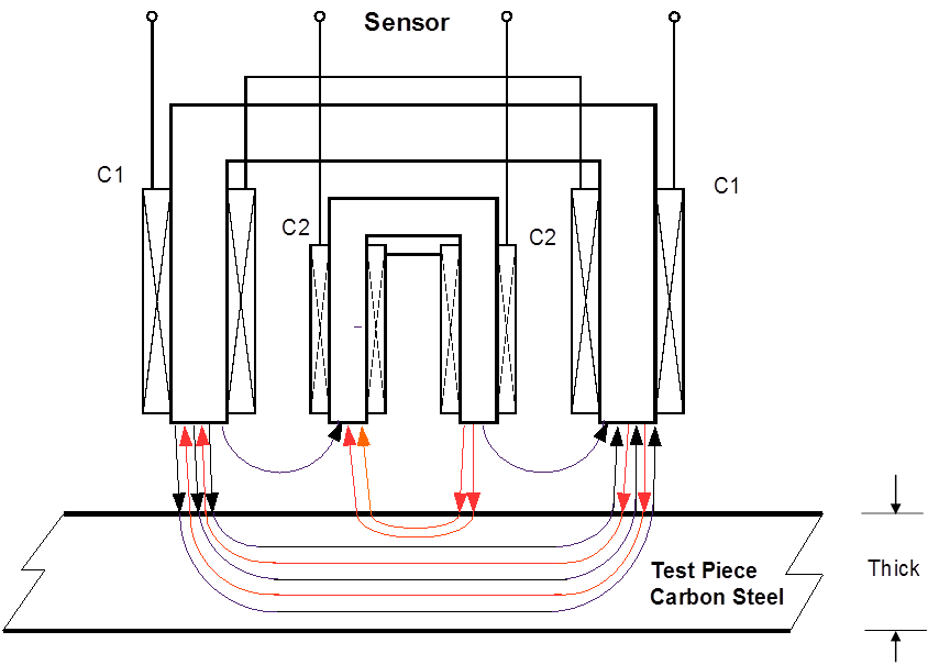
| Fig.1 Schematic Magnetic Flux Flow in Thick Wall Test Piece Black: Incident Flux Red: Flux by Eddy Current |
|---|
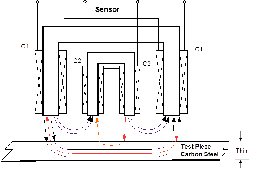
| Fig.2 Schematic Magnetic Flux Flow in Thin Wall Test Piece Black: Incident Flux Red: Flux by Eddy Current |
|---|
In the thin test piece, magnetic flux flow is shown schematically in Fig. 2. In this case, the incident flux penetrated into a thin test piece becomes less and, resultantly, the direct flux becomes relatively larger. Meanwhile, the magnetic flux generated by eddy current shows some delay in phase angle. The delay increases as the thickness or path length in test piece becomes larger. As a result, the voltage generated on detector coil C2 decreases in amplitude and its phase is delayed more in case of the wall of the test piece is thicker.
The configuration of test system using “i Eddy” is shown in Fig. 3.. Synthesized sine wave signals are generated digitally by computer and fed into “i Eddy”. The signal is converted by DAC (Digital to Analog Converter), and fed into coil C1 to excite it. Detected signal on C2 is sampled, and then converted to digital signal by ADC (Analog to Digital Converter), and amplitude and phase of the signal are analyzed and detected by FFT (Fast Fourier Transform) respectively. The wall thickness D of test piece is estimated by the linear estimation formula (1) using variables of measured amplitude Amp and phase Ph.
D=a Amp + b Ph+c (1)
Coefficients a, b and c are obtained by the calibration conducted in advance by collecting the data on 3 reference positions.
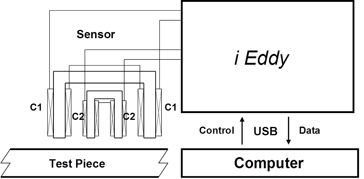
| Fig.3 Configuration of Test System |
|---|
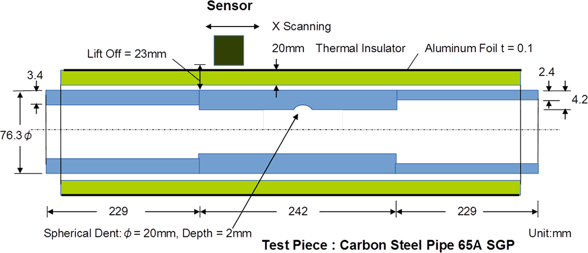
The picture of the test system is shown in Fig. 4. As shown in Fig. 4, sensor is positioned above the thermal insulator. It scans the pipe axially being towed by a belt driven by a stepping motor controlled by “i Eddy”. The axial position of the sensor is represented as X-ordinate, and total lift-off is maintained as 23mm.
Detail of a test piece, carbon steel pipe 65A SGP., is shown in Fig. 5. Normal wall thickness is 4.2mm, and both ends are artificially bored to wall thickness of 2.4mm and 3.4mm respectively. At center portion, a spherical dent is machined, 20mm in diameter and 2mm in depth. The test piece is covered by a thermal insulator, 20mm in thickness. The exterior of the insulator is covered by aluminum foil, 0.1mm in thickness.
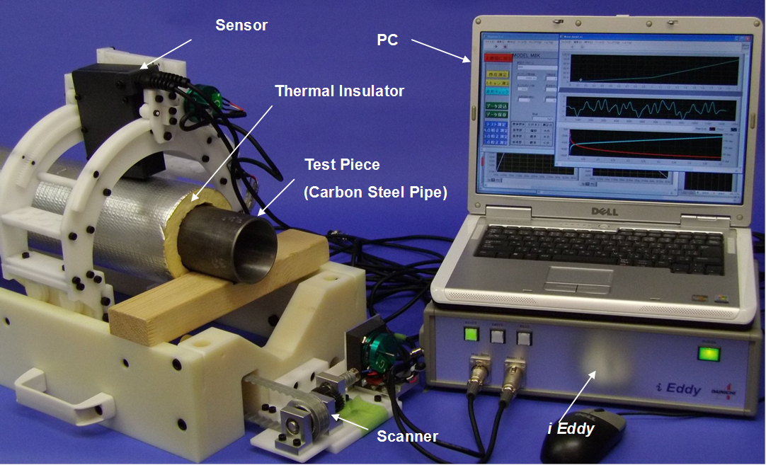
| Fig.4 Picture of Test Systems |
|---|
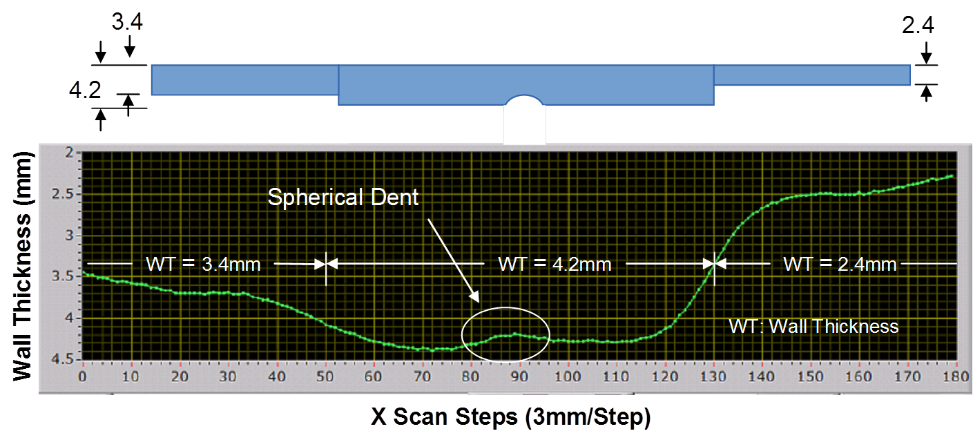
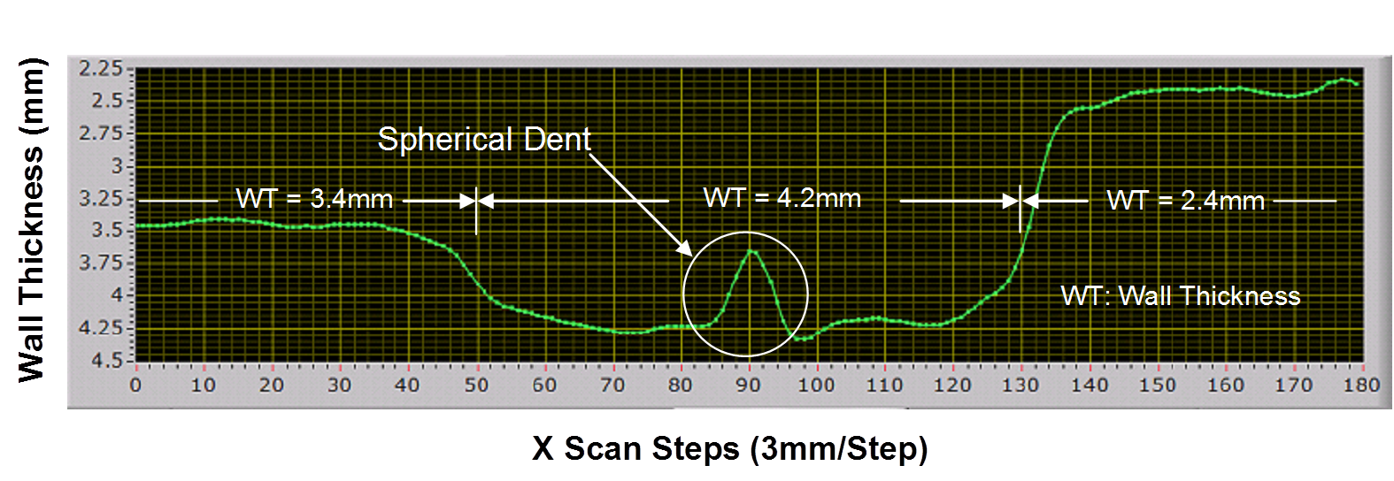
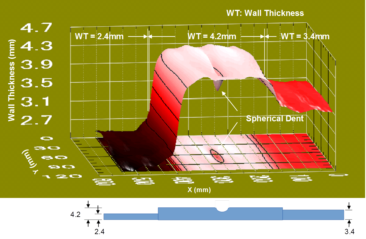
An example of test results is shown in Fig. 6. It shows that the change of the wall thickness is significantly indicated even at the large lift-off of 23mm. However, the spherical dent can only be indicated as a small hump. If such indication is recognized, it is recommended to conduct a closer check by removing the thermal insulator. If the lift-off is reduced to 2mm by removal of insulator, the dent can be clearly detected and indicated as shown in Fig. 7. If the circular scanning around the pipe is added as Y-ordinate, 3D image of wall thickness and dent can be obtained as shown in Fig. 8. In visualization in 3D image, it is convenient to identify the inner surface defect as a bird view as if it were looked down from inside of the pipe. Therefore, the picture in Fig. 8 is shown as upside down and horizontally reverse image comparing with Fig. 5, 6 and 7. By magnifying the 3D image, the dent at center portion can be displayed as a vivid 3D image with a projection to XY plane as shown in Fig. 9. This means that the system has a good signal to noise ratio and accuracy.
However, if the lift off is increased, the sensitivity is decreased as shown in Fig. 10. Figure 10 shows an example of data, the lift off vs. measured peak point corresponding to the dent portion in Fig. 6. As shown in Fig. 10, the limit of lift off would be 35mm or so in combination of current sensor and test piece..
| Fig.5 Details of Test Piece |
|---|
| Fig.6 Wall Thickness Screening Test Lift-Off: 23mm, Over Thermal Insulator, X scanning, Y: Center, f = 35Hz |
|---|
| Fig.7 Wall Thickness Precise Measurement Lift-Off: 2mm, X scanning, Y: Center, f = 35Hz |
|---|
| Fig.8 3D Visualization Lift-Off: 2mm, XY Scanning, f = 35Hz |
|---|
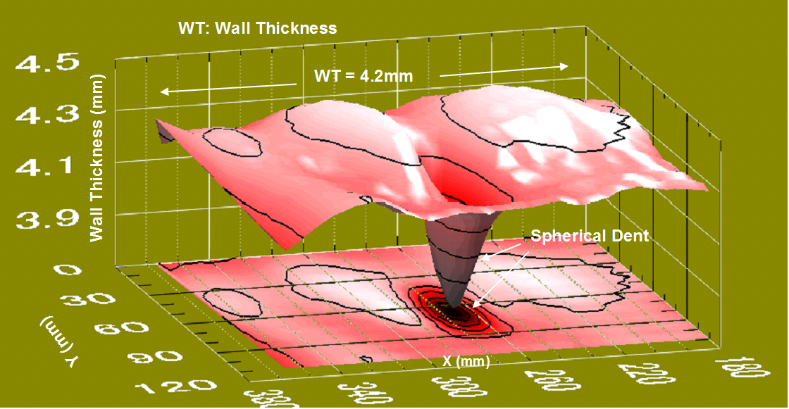
| Fig.9 3D Visualization, Detail in Center Portion (Artificial Dent) Lift-Off: 2mm, XY Scanning, f = 35Hz |
|---|
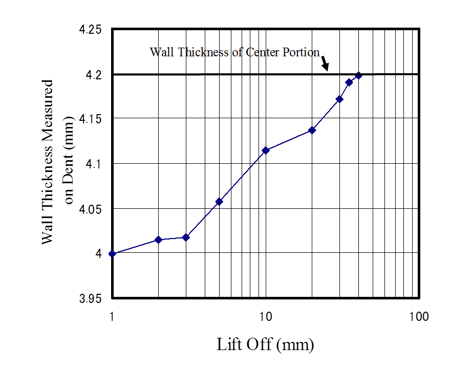
| Fig.10 Lift Off vs. Wall Thickness Measured on Dent in Center Portion |
|---|
Finally, it is emphasized that “i Eddy” system can be implemented to detect the change of wall thickness extended over some area even from the exterior of the thermal insulator. It is also useful to discover or screen local defects in maintenance inspection.
If some hump were found, direct measurement with smaller lift-off and representation of its results by 3D image visualization are more effective to identify and evaluate the defect.
- [1] K. NAKAMURA , A new approach to the Electromagnetic Induction Nondestructive Inspection –Preceding of Symposium in the Japan Society of Mechanical Engineers. No.11-49, pp.71-76, 2011-12-14~15