


Classification
2 - B(Condition Monitoring)
Presently, robots are deployed in the Fukushima Daiichi Nuclear Power Plant (NPP) for the implementation of survey, measurement and so forth of a working environment within the buildings by remote control under the high radiation environment. Additionally, it is anticipated that there will be an increasing need in the future for the robots to be used for the removal of debris, installation of shielding and so forth. Furthermore, it is deemed necessary to prepare the robots for the decontamination work required to improve the environment within the buildings, and to apply the robots also to the subsequent survey and repair works for reactor containment vessels.
To respond to such a need for the application of remote-controlled robots, development works have been in progress for a remote-controlled robot system utilizing wireless communication technology, a amma camera for the measurement of gamma-ray intensity distribution, a small-scale double-arm heavy machinery-type robot for disaster-handling use “ASTACO-SoRa” and a remote-controlled decontamination device by using high-pressure water “Arounder”, thereby promoting the development that enables appropriate measures to be taken towards site surveys, debris removal and an improvement in the environment.
This paper provides an introduction to the remote-controlled robot system utilizing wireless communication technology that is one of the above-mentioned robots developed thus far.
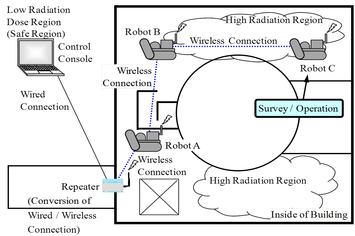
Fig.1 Composition of Remote-Controlled Robot System
Figure 1 shows the composition of this system. This system enables us to control three remote-controlled robots with one control console, and with the implementation of the relaying of inter-robots radio waves, this system allows operation even in a blind area. The application of such wireless communication technology makes it possible to conduct surveys in highly radioactive regions where the entry of workers is difficult under the situation of lack of communications infrastructures in disaster sites, and at the same time under the blind environment inside the buildings as well.
Phase 1 : Research and Development Phase
- (1)Components:
within the Reactor building / Turbine building
- (2) Location:
Floor, Stairs
- (3) Material:
N/A
- (4)Condition:
Disaster site, Radiation environment
- (1) Control of multiple robots by one console
Figure 2 shows the control console of this system. The selective switching of robots to be controlled is possible by a robot control screen, which displays the pictures from a survey camera mounted on the robot selected for control, and the pictures and others from overhead cameras in front and behind. It is intended that the pictures from cameras needed for the control of operation are selectable from the pictures from cameras on a monitor, thus assisting operators in controlling the robot. In addition to displaying the velocity setup and operating state of the robot selected, the monitoring values of the information (radiation dose, temperature, humidity) derived from the sensors mounted on three robots are displayed at all times, thus making it possible to monitor site conditions at all times.
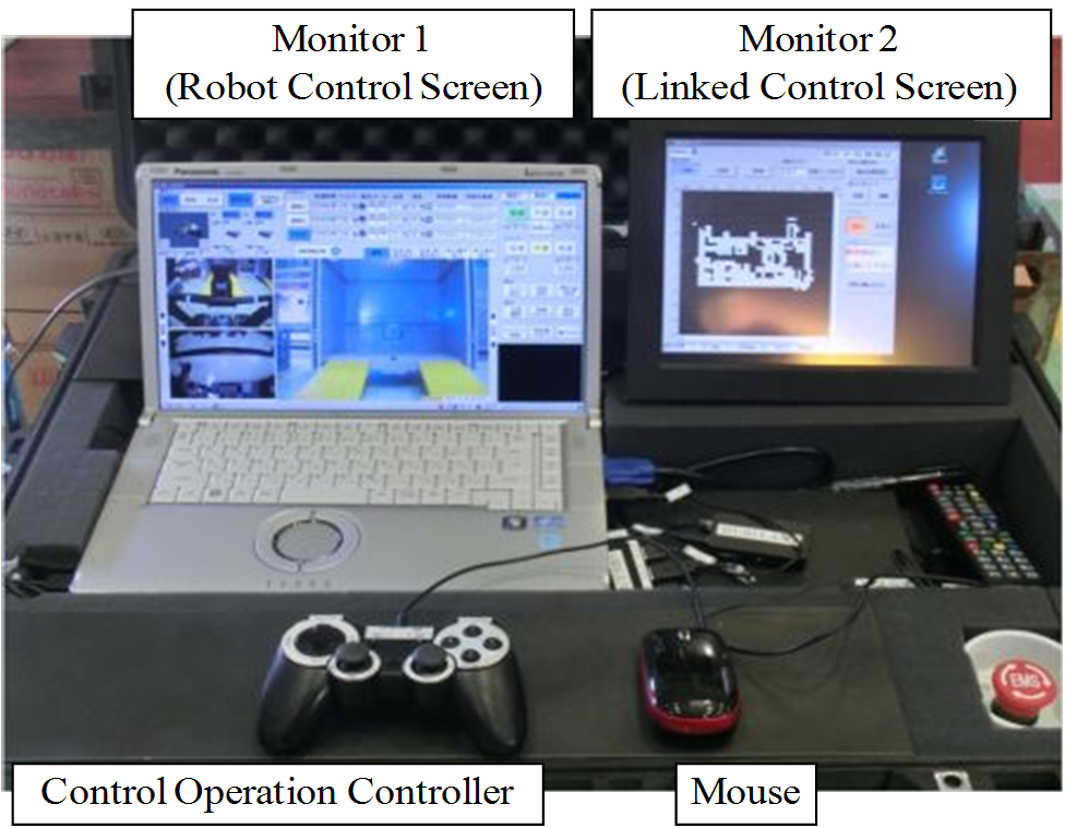
Fig.2 Outer Appearance of Control Console
- (2)Utilization of low frequency bandwidth
In recent years, the utilization of wireless LAN conforming to the IEEE standard has been promoted as a communication technology used for making robots wireless. However, the frequencies stipulated in wireless LAN are in the bandwidth of 2.4 GHz and 5.2 GHz that make high speed communication possible, but these frequencies make it difficult to expect radio waves to take a roundabout path within the buildings due to the their strong linearity, resulting in the need to operate within the range visible from transmitters. In contrast, the frequencies for wireless communications used for this system are in the low frequency bandwidth (200 MHz or so) for wireless LAN, thus it is possible to secure a wider range of access for radio waves including the radio waves taking a roundabout path to walls inside the buildings, layout of equipment and so forth. These frequencies are considered effective for moving robots to ensure their communication stability and motion range.
- (3)Utilization of map function
Laser sensors are mounted on the moving robots functioning according to this system, and the measurement of surrounding conditions while moving makes it possible to know their self-locations. Self-location data enables us to avoid interaction with obstacles and inter-robot collision by a linkage with surrounding map information.
With the map displayed on linked control pictures of a control console divided into meshes that is followed by the registration of travelling information in each mesh, this map information contributes to the mitigation of burdens on operators in terms of assisting them in knowing the robot locations and the state of obstacles.
Figure 3 shows “Robot control screen”, and figure 4 shows “Linked control screen”.
The SLAM (Simultaneous localization and mapping) unit on the Robot simulates map-matching from the map data and the distance to the obstacles measured by the laser sensor, and sends calculated present position and direction (x, y, θ). This method makes it possible to reduce communication load between the control console and the robots and know the present position of the robots in real time.
Figure 6 shows the map data on the robot. First, the map data will be made from the CAD data (Fig.6 (1)) but after first entry, the map data will be renewed from scanned data by the robot (Fig.6 (2)). This can improve the accuracy of the map-matching simulation from the second approach.
Figure 7 shows the example of the map function application. This system has the interlock function that stops the Robot A automatically with warning message on the linked control screen if the Robot B is on the way of the Robot A direction when the Robot A is operated
In the past, the three robots have been applied in the above system. And the verification tests in the simulated disaster site for following functions have been performed and anticipated performance was confirmed.
(1) Remote control operation of the three robots and selected robot switching function(2) Wireless communication and relay function
(3) Linked control function (Obstacle alarm and inter-robot collision prevention interlock)
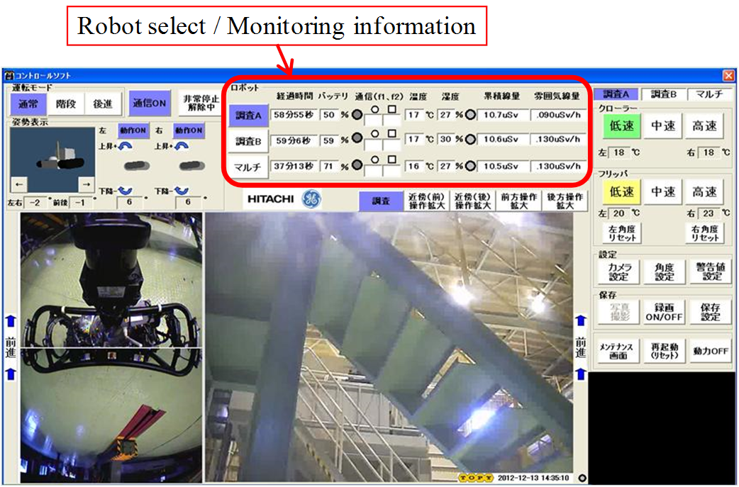
Fig.3 Robot control screen
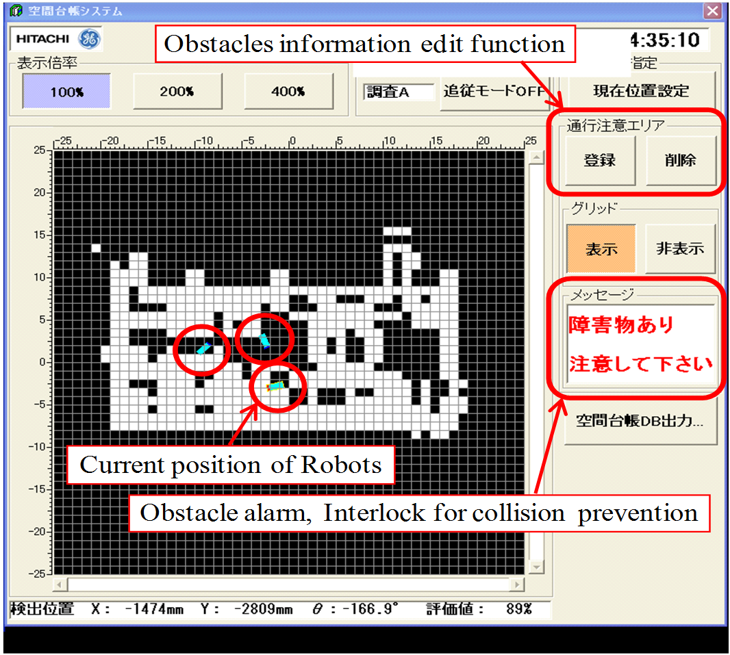
Fig.4 Linked control screen
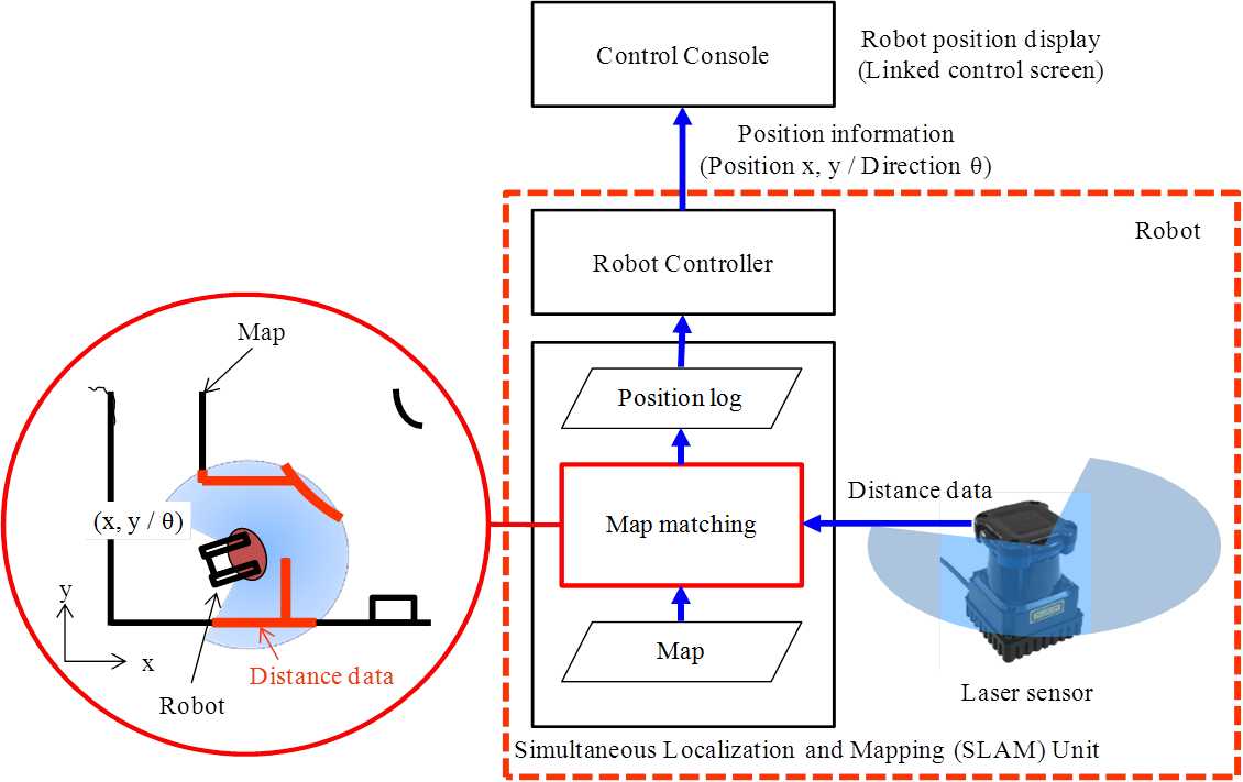
Fig.5 Composition of SLAM function
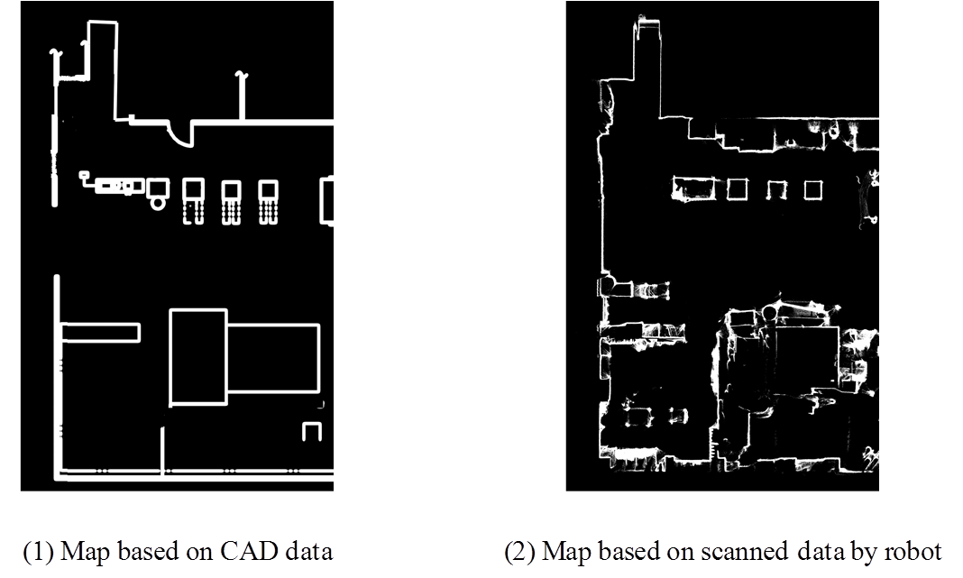
Fig.6 Examples of Map data on the Robot
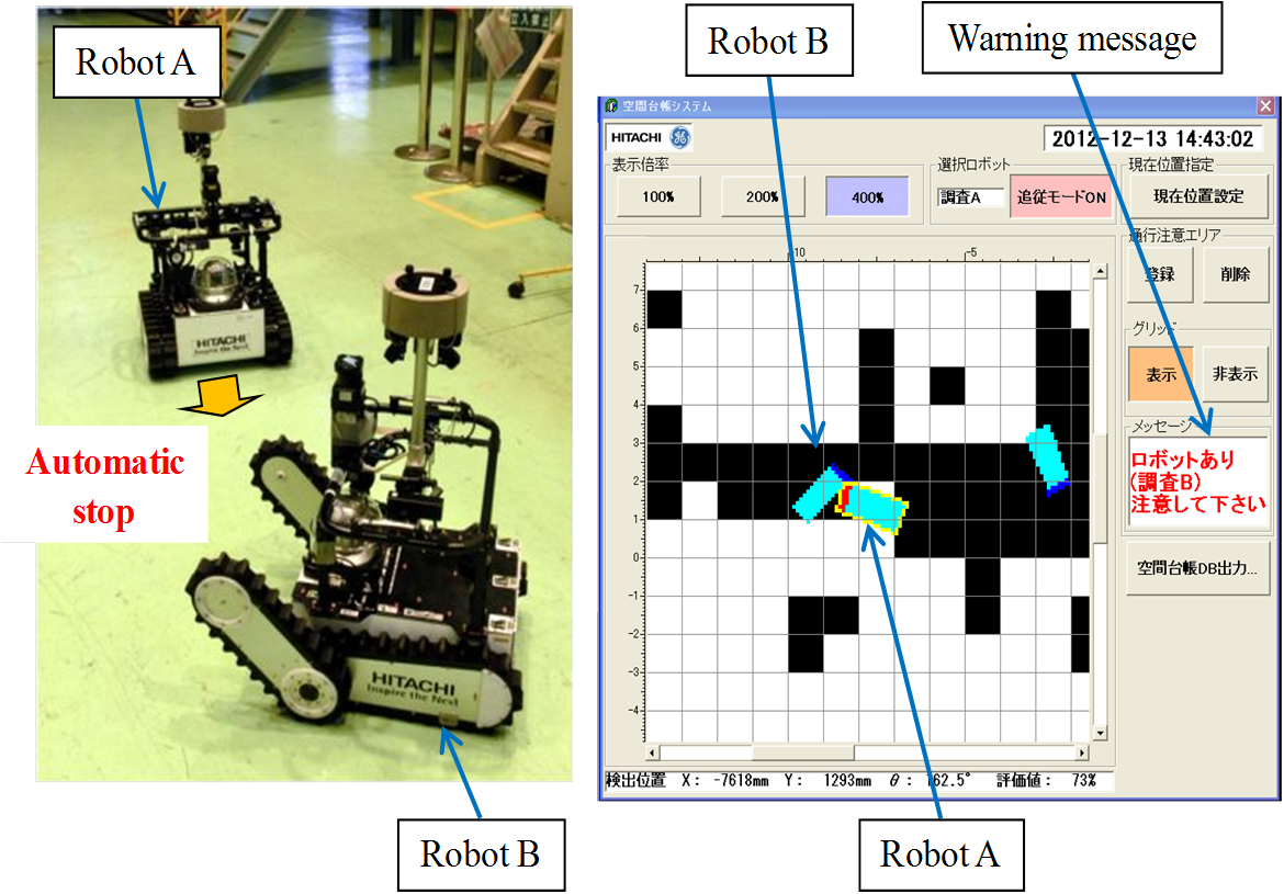
Fig.7 Inter-robot collision prevention interlock function
- [1] Y. Kometani: Development of remote device which contributes to the environmental improvement in the nuclear disaster site, Electrical Review, June 2013, pp.34-38 (2013)
The Remote Control Monitoring Robot System introduced in this paper has been developed as part of the contract research “Research and Development of Life-Support Type Robot System” sponsored by the Ministry of Internal Affairs and Communications (*)aiming for a network robot verification system in nuclear power plants.
(*)“The Ministry of Internal Affairs and Communications” is the administrative agency of Japan.