


Classification
1 - A
Phased Array Ultrasonic Testing (PAUT), which can vary its refraction angle and so forth by pulsing multiple elements of a probe separately, has been applied to many components as a superior alternative technique for a conventional single element probe testing [1-3].
However, it was known that PAUT was difficult to apply to components with complex surface geometry such as a complex shaped structure and/or a non-smoothened surface structure formed by welding and/or grinding, because the setting of the probe on the surface or the control of the refracting angle was not possible. To solve this problem, various PAUT technologies have been developed. Major countermeasures are a probe shape deformation method using flexible probe [4,5] and an ultrasonic beam control method. Although the probe shape deformation method is effective, it has many problems for the field application because the probe shape should be developed for each case and these probes are expensive. The ultrasonic beam control method has an advantage in using the existing and proven array probe, but it has also many issues to apply in the field. This method requires surface profile measurement and appropriate medium that couples between the probe and the surface of inspected component in case of inspection in air. Although partly in water inspection methods were developed [6,7], these have also many problems to become widely used for using complex equipments.
Toshiba has developed a ultrasonic beam control PAUT technology itself and that with easily formable gel (soft shoe) as propagation medium [8-11]. The schematic diagram of the application to R60 (Radius of curvature 60mm) nozzle is shown in Fig.1. In case that the conventional PAUT applies to R60 nozzle, incident ultrasonic beam is reflected diffusely or refracted with incorrect angle because of the surface profile (Fig.1 (a)). In case of newly developed PAUT, incident ultrasonic beam refracts in correct angle (Fig.1 (b))
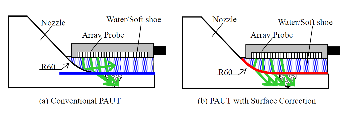
Fig. 1The schematic diagram of the application to R60 nozzle
The inspection procedure by using this technique is shown in Fig.2. Before inspection, there are two steps; surface profile measurement and calculation of delay time depending on surface profile. In surface profile measurement, ultrasonic wave is transmitted by each element that composes array probe. Reflected ultrasonic wave on measurement surface is received by all elements (from “element 1” thru “element n”). Therefore n×n patterns for raw wave pattern will be acquired. Intensity of reflecting waves from material surface is visualized by the Synthesis Aperture Focusing Technique (SAFT) using this wave patterns. This method enables higher precision surface profile measurement.
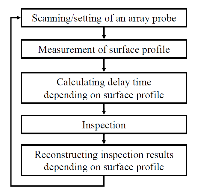
Fig. 2 Inspection procedure
The schematic diagram of controlling ultrasonic beam to inspect partly dented surface is shown in Fig.3 for illustration. In case of the conventional PAUT, the delay time is controlled by the assumption that the surface is flat. Therefore the refracting angle deviates from the right direction shown as the red line in Fig. 3 (a) because the ultrasonic beam is diffused with the same delay time. In this case, inspection refracting angles are changed by surface profile as Fig.3 (a). In this figure, green line shows successfully and accurately aimed ultrasonic beam, red line shows failed and uneven incident angle of ultrasonic beam because of curved surface.
In case that the delay time is calculated after fixing positions of a drive element and its paired focus (like the conventional linear scan) even if only the surface profile is compensated, although the ultrasonic beam can be incident on focus, the refracting beam deviates irregularly from the right direction with parallel angle shown as the red line in Fig.3 (b). Toshiba has succeeded in controlling ultrasonic beam to enter into the material in the right direction corresponding to surface profile. In this technology, firstly the focus point and inspection refracting angle are determined, then the incident point and optimum incident angle are uniquely determined. Lastly the elements are determined as driven elements on the incident angled extension line. This method makes it possible that ultrasonic beams in material are controlled to refract parallel to each other as shown in Fig.3 (c).
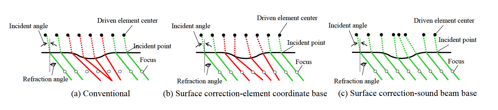
Fig. 3 Schematic diagram of controlling ultrasonic beam
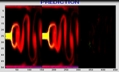
The simulation result in the ultrasonic field controlled to inspect the R60 nozzle is shown in Fig.4 [8-11]. Fig.4(a) shows the ultrasonic field produced by incident ultrasonic beams with the delay time calculated for flat surface. Similarly, the ultrasonic field produced by the incident ultrasonic beams with the delay time calculated depending on the surface profile. It was verified by the simulation that the ultrasonic field is controlled and focused accurately by the incident beams with the delay time calculated depending on the surface profile.
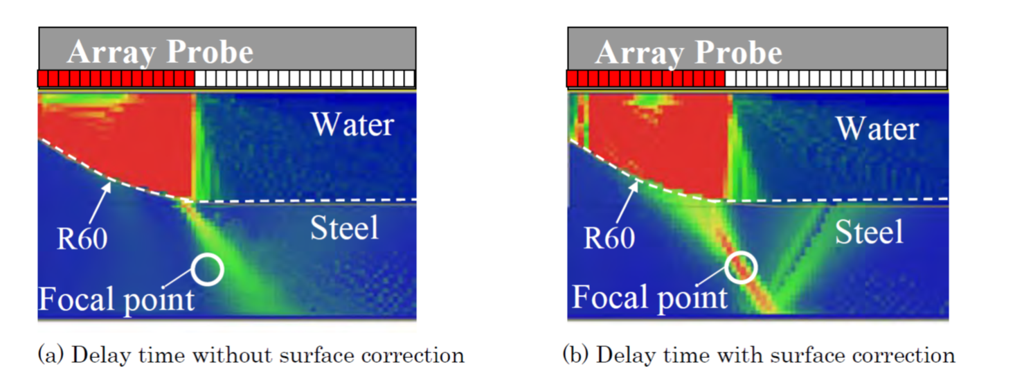
Fig. 4 The calculated ultrasonic field to inspect R60 nozzle
In addition, a soft shoe made by hydro-gel has been developed to inspect in air. The soft shoe has similar acoustic properties to water, the sound speed in which is 1450 m/s and the specific gravity is 0.82. Inspection sensitivity using this soft shoe is about 6dB less than the immersion method. With only gain control, inspection accuracy of this method achieves the same level as immersion method. Though the inspection for R60 nozzle is only taken up as an example to illustrate this technique here, it is also applicable to the distorted surface by welding or the curved surface by grinding.
Phase 2 : Industrial Confirmation Phase
- (1) Components: Reactor Pressure Vessel / RPV internals and heat exchangers in BWRs and PWRs
- (2) Location: Complex shaped component (i.e. Nozzle, Pipe, Nozzle welded part)
- (3) Material: Stainless steel, Carbon steel, Nickel based alloy
- (4) Condition: Under water or in air
- (1) Inspection for three (3)dimensional inspection
Without designing and manufacturing new probe particular to the inspection surface geometry, the detection and sizing of the defect in components are possible [10,11]. And this technology has been expanded to apply to three (3) dimensional (3D) surfaces using the matrix array. The matrix array probe makes it possible to inspect 3D complex shaped structures/components.
- (2)High speed three (3)dimensional inspection
Parallel receiving circuit for the 256ch waves and high speed data transmission circuit (500MB/s) between PC and wave processor have been developed to achieve bi-directional communication of n×n patterns raw waves high speed 3D surface profile measurement and fault detection/measurement [11].
- (3)Application in air using the soft shoe
The soft shoe that has similar acoustic properties to water and is able to contact the material has been developed. With using the soft shoe, it makes possible to inspect in air in the same way as under water [8-11].
- (4)Qualification test by the third party
It is possible to inspect using the phased array probe proven for many components according to Japan Electric Association Code (JEAC4207-2012). And this technology was qualified by Japan Power Engineering and Inspection Corporation (JAPEIC). It was confirmed that this technique is applicable to curved surfaces with more than R60 radius.
(1) Vessel nozzle inspection
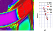
The result of the surface profile measurement on R60 nozzle is shown in Fig.5. along with the results of laser displacement measurement defined as the true (reference) value. Comparing the results using by Time of Flight (TOF) and Synthesis Aperture Focusing Technique (SAFT) to the true value, while the mean error of TOF is 0.98mm, that of SAFT is 0.05mm or less.
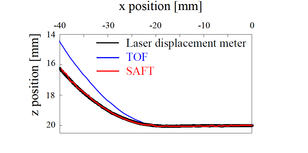
Fig. 5 Comparison of surface measurement accuracy
The inspection results of nozzle shaped specimen are shown in Fig.6. Fig 6 (a) shows a result of the conventional PAUT where the delay time is calculated for flat surface. The spurious echo is observed and the slit corner echo is unclear. Fig.6 (b) shows the inspection result in which the PAUT delay time is compensated for actual surface geometry. The spurious echo is suppressed and the slit corner echo is observed clearly.

Fig. 6 Inspection result of nozzle shaped specimen
(2) Expansion to 3-dimensions and modification for the application to the tee joint of the Core Spray (CS) Pipe
This technology has been expanded into 3-dimensions by using matrix array probe. The inspection result is shown in Fig.7. Test specimen is R60 spherical material with 50mm in thickness shown in Fig. 7 (a). Fig 7 (b) is a result of the conventional PAUT, where the delay time was calculated for flat surface. To evaluate the capability of the PAUT, the test specimen has drilled holes. The conventional method cannot observe the drilled holes echo at all. The bottom echo is not observed. Fig.7 (c) is the PAUT result in which the delay time was calculated for actual surface geometry. The bottom echo is observed clearly.
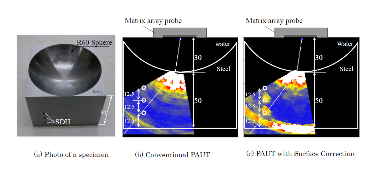
Fig. 7 Inspection result of nozzle shaped specimen
The application of this technology to the welded tee joint of CS Pipe is shown in Fig.8 as an example. Although it had been difficult to inspect it because of the complex shape, this technology has made it possible to defect any near weld line.
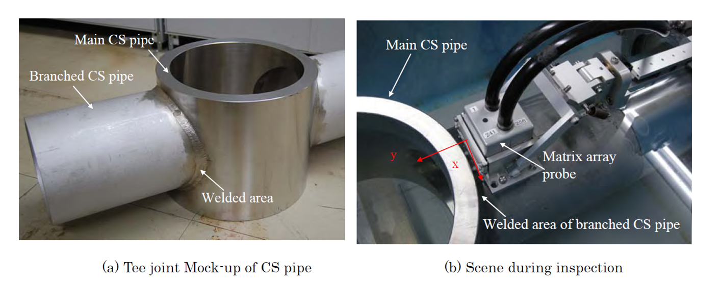
Fig. 8 Inspection of the welded tee joint of CS pipe
(3) Application of PAUT using the soft shoe in air
The set up of the inspection using the soft shoe is shown in Fig.9. The soft shoe is elastically deformed to fit the curved surface profile by pressing. For example of this application, Fig.10 shows an inspection configuration on nozzle weld mock-up of residual heat removal (RHR) heat exchanger in BWR plants using a matrix array probe and a soft shoe. It was difficult to inspect nozzle weld circumferentially from view points of a conventional probe setting and acoustic field control capability. The new PAUT technology was confirmed its inspection capability in air and the inspection for the actual BWR plant was conducted.
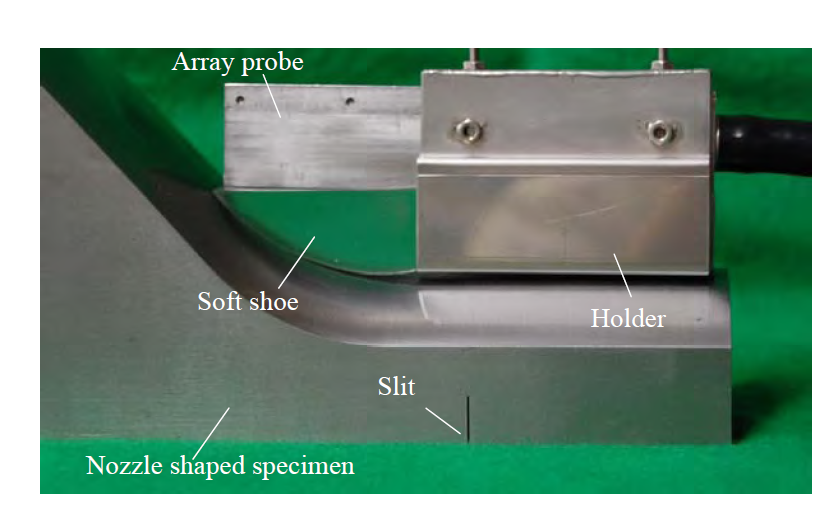
Fig. 9 Inspection setup using soft shoe
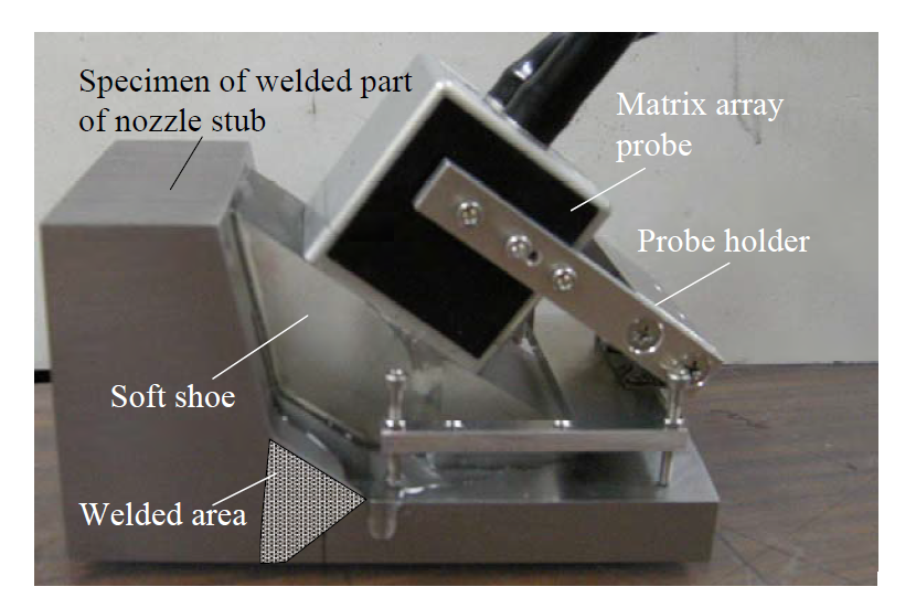
Fig. 10 Inspection of nozzle weld (Exa
- [1]T. Mori, H. Kashiwaya, K. Uchida, I. Komura and S. Nagai: Phased Array Type Ultrasonic Inspection Method and Equipment、Journal of the Japan Society of Mechanical Engineers、87(793)、pp.1341-1346 (1984)
- [2] I. Komura, S. Nagai, H. Kashiwaya, T. Mori and M. Arii ; Improve Ultrasonic Testing by Phased Array Technique and its Application, Nuclear Engineering and Design, 87, pp.185-191 (1985)
- [3] I. Komura, S. Nagai and J. Takabayashi ; Water gap phased array UT Technique for Inspection of CRD Housing/Stub Tube Weldment, Proc. of 14th Int. Conf. on NDE in Nuclear Industry, pp.305-310 (1996)
- [4]S. Mahaut, O. Roy, C. Beroni and B. Rotter; Development of Phased Array Techniques to Improve Characterization of Defect Located in a Component of Complex Geometry, Ultrasonics 40 pp.165-169 (2002)
- [5]O. Roy, S. Mahaut, and O. Casula ; Control of the Ultrasonic Beam Transmitted Through an Irregular Profile using a Smart Flexible Transducer: Modelling and Application, Ultrasonics 40 pp.243-246 (2002)
- [6]R. Long and P. Cawley ; Phased Array Inspection of Irregular Surfaces, Review of Progress in Quantitative Nondestructive Evaluation ,25, pp. 814-821 (2006).
- [7] J. Russell, R. Long, and P. Cawley ; Development of a Membrane Coupled Conformable Phased Array Inspection Capability, Review of Progress in Quantitative Nondestructive Evaluation ,29, pp. 831-838 (2010).
- [8]T. Miura, S. Yamamoto, M. Ochiai, T. Mitsuhashi, H. Adachi, S. Yamamoto and N. Suezono:Development of Phased Array Inspection Technique for Nozzle Pipes with Curved Surface, Proceedings of 7th Japan Society of Maintenology Annual Conference,, pp.50-54 (2010)
- [9] S. Yamamoto, J. Senboshi, M. Ochiai, T. Mitsuhashi, H. Adachi and S. Yamamoto: Shape Adaptive Beam Steering Technique for Phased Array Ultrasonic Testing, 38th Annual Review of Progress in Quantitative Nondestructive Evaluation, Burlington, VT, July 17-22 (2011)
- [10]S. Yamamoto, J. Semboshi, M. Ochiai, T. Mitsuhashi and S. Yamamoto: Beam Steering Phased Array Ultrasonic Testing Technique for Curved Surface Shape, Proceedings of JSNDI Spring Conference 2012, pp.19-22 (2012)
- [11]S. Yamamoto, J. Semboshi, T. Miura, T. Mitsuhashi and M. Ochiai: Beam Steering Phased Array Ultrasonic Testing System for Complex Surface Shape Strucutures, Journal of The Japanese Society for Non-Destructive Inspection, Vol.62(2), pp.95-101 (2013)
Japan Society of Maintenology (ejam@jsm.or.jp)