


Kyushu Electric Power Co., Inc.
Organo Corporation
Vol.3, No.1, NT33
Evaluation of High Flow Rate Condensate Polisher for Next PWR Plants
KEYWORDS:
Condensate Polisher, Vessel, Distribution, BTC(Breakthrough Capacity), Ion Exchange, Downsizing
1. Technical summary
Classification
5 - A Performance improvement
Pressurized water reactor nuclear power plants (PWRs) of Kyushu Electric Power Co. have a full-flow condensate polisher to meet or exceed the water chemistry requirements for feedwater and steam generator water in all operation modes.
For the design of next new PWRs, the high flow rate condensate polisher is projected to reduce the number of demineralizing vessels and to downsize the condensate polishing system. In this paper, ‘High flow rate condensate polisher’ means the polisher which is about twice the flow rate of conventional polisher. Prior to the adoption of the high flow rate condensate polisher for next new PWRs, the ion exchange performance and the validity of the design for the vessels are evaluated.
As a result of the evaluation by column test, it is verified that the ion exchange performance of high flow rate condensate polisher is comparable to that of the conventional condensate polisher even at the maximum flow rate, and it can treat the condensate without deterioration of effluent water quality. Moreover, it was confirmed that the structural modified vessel could maintain the fluid stability and provide the adequate strength for high flow rate operation by fluid flow analysis.
2. Development phase
Phase 1 : Research and Development Phase
3. Scope
- Components: Condensate Polisher
- Location: Inner Structure of Vessel, Piping
- Materials : SB410, SUS304
- Condition: Same as Design Conditions of Condensate Polishing System
4. Features
-
Downsizing of Condensate Polishing System
The flow rate (LV: Linear Velocity) of the conventional polisher is approx.100m/h. High flow rate condensate polisher has the structural modified vessel which can maintain a uniform flow distribution. By the adoption of the structural modified vessel, the flow rate can be increased to about twice the rate of conventional polisher. It means the flow volume per vessel can be increased to about twice the volume of the conventional vessel and so the number of vessels can be reduced to a half of the conventional vessels as shown in Figure 1. The high flow rate condensate polisher needs the same regeneration system as the conventional one, but still it can reduce the installation space and the capital cost greatly.
Fig. 1 The image of downsizing by the adoption of structural modified vessel.
-
Ion Exchange Performance
Ion exchange resin performance has been confirmed by the column test in the range from LV10m/h to 250m/h. As shown in test results, the high flow rate condensate polisher can maintain enough ion exchange capacity and effluent quality even at the 200m/h flow rate.
-
< Test Condition >
Dependence on flow rate of ion-exchange performance was examined by the column flow test.
This test was performed for the linear velocities of 80,200 and 250 m/h under water chemistry conditions at start-up, shutdown and condenser in-leakage of sea water. 80 m/h is for the full flow of conventional condensate treatment, and 200 and 250 m/h are for the high flow rates.
LV10m/h and LV20m/h are the tests assuming the case of the high AVT operation, in which the condensate polisher treats SG blowdown instead of the condensate and the condensate is bypassed.
-
< Test Results >
The relation between BTC (Breakthrough Capacity) and LV (Linear Velocity) is shown in the Figure 2. BTC is a value of ion exchange capacity of a resin.
・Dashed lines in the Figure 2 show Quality criteria for cation exchange resins and anion exchange resins. BTC values are larger than Quality criteria under the all test conditions.
・LV dependence with BTC is not observed under the all test conditions.
・Effluent impurities of new resin column are kept at low level under all LV conditions.(Table 1)
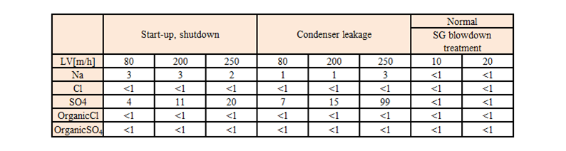
・Effluent impurities of degraded resin column are kept at low level under the low LV conditions. However, the degraded resin has the tendency to leak more SO4 at the high flow rate. But it is no problem in terms of impurity elimination. (Table 2)
Fig. 2 Dependence on flow rate of Breakthrough Capacity of Condensate Polisher resin
Table 1 Effluent Quality of New Resin Column (ppt)
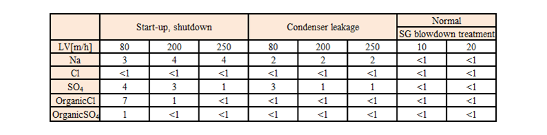
Table 2 Effluent Quality of Degraded Resin Column (ppt)
-
Improvement of Fluid Stability
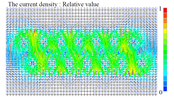
Newly designed vessel can maintain a uniform flow distribution and keep the resin layer stable. The results of simulated flow analysis are shown in Figure 3 and 4. Even at LV 250 m/h, which is a maximum flow rate of high flow rate condensate polisher, the newly designed vessel can keep surface of resin layer stable. Meanwhile, the horizontal flow of the existing vessel must be over 100m/h (0.028m/s) at that the drift of resin layer could occur in this condition.
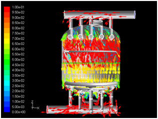
Fig. 3 Vector Diagram and Horizontal Flow Velocity of Conventional Vessel at 250m/h
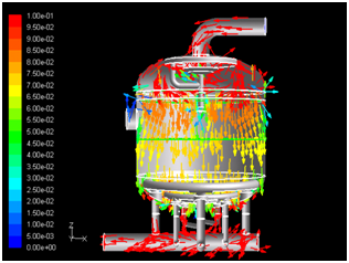
Fig. 4 Vector Diagram and Horizontal Flow Velocity of Newly Designed Vessel at 250m/h
5. Examples of Application
None
6. Reference
S. Haraguchi, K. Chouchi and H. Asano, Kyushu Electric Power Co., Inc. and S. Ohashi, K. Yamada and T. Kosuga, Organo Corporation “Evaluation of High Flow Rate Condensate Polisher for Next PWR Plants”, Poster of Symposium on Water Chemistry and Corrosion in Nuclear Power Plants in Asia 2009, Nagoya, Japan
7. Contact
Japan Society of Maintenology (ejam@jsm.or.jp)