


Hitachi-GE Nuclear Energy, Ltd.
Hitachi, Ltd.
Vol. 12, No. 1, NT97
Ultrasonic Underwater Imaging Techniques
for Visualizing Environments and
Supporting Remote Operation
KEYWORDS:
Ultrasonic underwater imaging, Remote operation, Turbid water
1. Technical summary
Classification
7 - C
This paper describes a proposed underwater imaging techniques and the verification by a small-scale mock-up. Since the Great East Japan Earthquake and Tsunami in 2011, internal survey techniques have been demanded to facilitate the planning and the actual decommissioning of the Fukushima-Daiichi Nuclear Power Station [1]. As a complement to optical methods, ultrasonic underwater imaging techniques are important for recognizing the environment status and identifying the obstacles for supporting remote operation in turbid water. Therefore, the underwater ultrasonic imaging techniques have been developed based on the ultrasonic phased array techniques utilized in the nondestructive testing field. A method that combined a convex array sensor with a defocusing acoustic lens was proposed for wide area imaging. The imaging techniques are described in detail in Section 4. As a result of a mock-up experiment, the acoustic shape image of an object separated by about 4 m from the sensor was obtained and the 20-mm frame of object were identified.
2. Development Phase
3. Scope
- (1) Components:
Plant, Remote control equipment
- (2) Location:
Underwater environments
- (3) Materials:
N/A
- (4) Condition:
N/A
4. Features
In this section, measurement technologies are described to visualize environments in turbid water. Fig. 1 shows overview of an ultrasonic imaging techniques that we proposed. The beam scanning method is shown in Fig. 1 (a). Ultrasonic beams are focused in a direction parallel to the element array direction and defocused in a direction perpendicular to it by using an acoustic lens. The spread angle of the beam by the acoustic lens is designed depending on space of applied work environment. Each beam has a thin fan shape and is scanned electrically in a manner similar to that of sector scanning. Fig. 1 (b) describes how to obtain shape of an underwater object. The information on the surface shape of the object is obtained as the difference of time-of-flight in each spread fan beam. This is a similar method to that used for acoustic lens sonar devices [2][3]. The echoes from the object are identified by the time-of-flight such as t1, t2, and t3. The three-dimensional image is obtained by using the echoes of each scanned beam.
Here the details of the convex array sensor and the beam scanning method are explained. The array sensor has multiple sensor elements arranged on a convex curved surface, and the effective aperture size is the same at each scanning angle as shown in Fig. 2. Therefore the same beam width is generated for each scanning angle. Fig. 3 shows the principle of transmitting and receiving an ultrasonic wave using the array sensor. The sensor elements generate an ultrasonic beam by controlling delay time. The ultrasonic beam is electronically scanned by changing the set of sensor elements and the delay time. When there is a reflector in the focusing area, the reflection signals are received by the elements and the received signals are synthesized by phase matching.
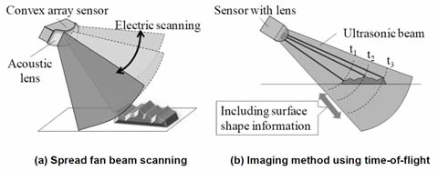
Figure 1 Overview of ultrasonic imaging method using convex array sensor and lens
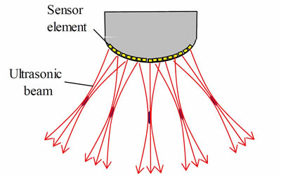
Figure 2 Features of a convex array sensor
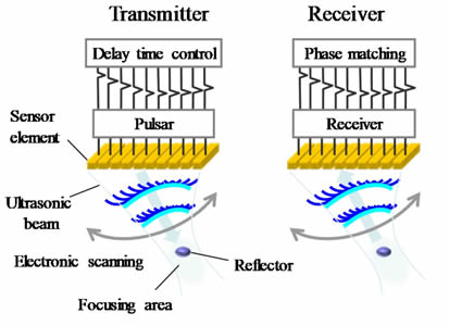
Figure 3 Principle of transmitting and receiving an ultrasonic wave
5. Example of Application
A grating panel and a cylindrical weight were measured by a confirmation experiment of the imaging performance. The experimental setup is shown in the schematic diagram in Fig. 4(a) and the photos in Fig. 4(b). The convex array sensor with an acoustic lens and a reflection target were set in a water tank. The ultrasonic beam was generated by a controller (PC) and the control unit including pulser/receiver. The frequency of the ultrasonic wave was set in 2 MHz on the consideration of the transmission in water. The electronic scanning angle was set in between -20 degrees and +20 degrees and the spread angle of fan beam was set in approximately ±10 deg. The objects to be measured were located far from the ultrasonic array sensor by about 1m. Here the frequency of the ultrasonic wave and the effective aperture size of the array sensor are determined depending on the measurement distance and the spatial resolution needed for applications.
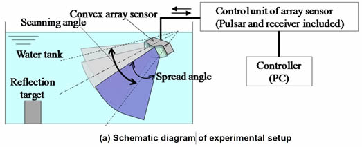
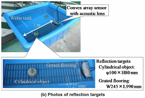
Figure 4 Configuration of experimental setup and reflection targets
The photos of the reflection targets and the measurement results of the ultrasonic imaging are shown in Fig. 5. The ultrasonic image is displayed as a bird’s-eye view with a three-dimensional effect. From the results, the white dots and the blue dots show that received signal intensity is high and low, respectively. From the experimental results, the shape of the cylindrical object and the grating panel were recognized. A wide region was visualized with the three-dimensional effect although the electronic scanning was only one-dimensional convex scanning of the spread fan beams. Furthermore, the spatial resolution was at least 25 mm because the 25-mm spacing of the grating panel was identified.
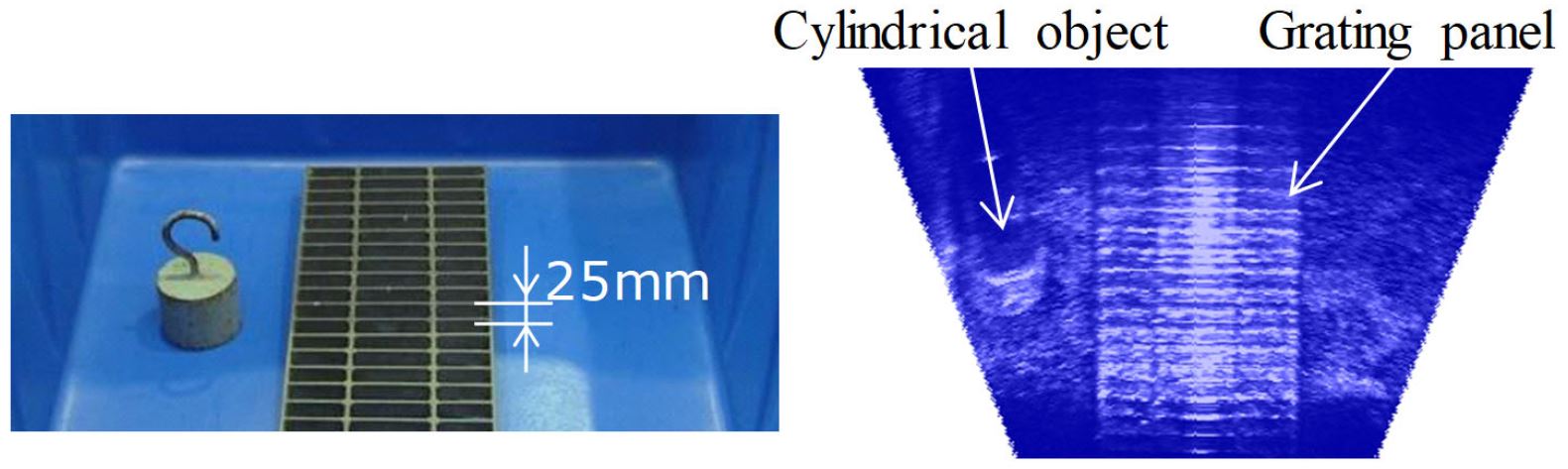
Figure 5 Measurement results of our proposed imaging method
We also evaluated the performance of the long-range measurements. Fig. 6(a) shows the experimental setup. The ultrasonic sensor and the reflection targets were located in a water tank. A ladder-shaped object and a H-shaped object were used as the reflection targets as shown in Fig. 6(b).
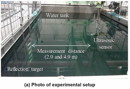
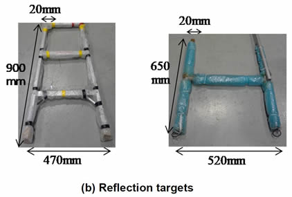
Figure 6 Experimental setup in long-range
Fig. 7 shows the long-range measurement results. For 2.0 m and 4.0 m of the measurement distances, the reflection target images were obtained in real-time. Moreover the 20-mm frames of the reflection targets were recognized as shown in Figs. 7 (a) and (b).
Therefore the developed imaging technique was found to have sufficient performance to visualize the working environments and support the remote operations.
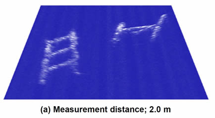
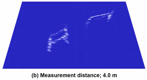
Figure 7 Measurement results in long-range
6. Reference
- 1.Hitachi, Ltd., “Submersible crawling swimming and shape-changing robots for inspection prior to removal of fuel at Fukushima Daiichi Nuclear Plant – Changing shape and posture to avoid obstacle in narrow space --”, http://www.hitachi.com/New/cnews/month/2014/03/140310e.html, Press Release, posted on March 10, 2014.
- 2. E. O. Belcher, et al., “Object identification with acoustic lenses”, OCEANS, 2001. MTS/IEEE Conference and Exhibition, vol.1, pp.6-11, 2001.
- 3. E. O. Belcher et al., “Dual-frequency acoustic camera: a candidate for an obstacle avoidance, gap-filler, and identification sensor for untethered underwater vehicles”, OCEANS, 2002. MTS/IEEE Conference and Exhibition, vol.4, pp.2124-2128, 2002.
7. Contact
Japan Society of Maintenology (ejam@jsm.or.jp)