


Mitsubishi Heavy Industries, Ltd.
Vol. 11, No. 4, NT96
The Development of Sampling Technology inside Reactor Vessel and Core Internal during PWR Decommissioning of Japan
KEYWORDS:
Decommissioning, PWR, sampling, reactor vessel, Core internal, Mihama Unit 1&2, Genkai Unit 1
1. Technical summary
Classification
7 - A
The course of decommissioning was classified into four stages; dismantling preparation, reactor auxiliary component dismantling, reactor area dismantling, and building dismantling. The permission and authorization for each stage are planned to be applied for in a stepwise manner.
Components in the reactor core area have been highly radio-activated due their long term operation. And they still have high dose rates even after physically and chemically decontaminating radioactive corrosion products attached on their surface. Various samples need to be taken from Reactor Vessel (hereinafter called R/V) and Core Internal (hereinafter called C/I) to acquire information on their radio-activation distribution for the purpose of establishing the appropriate decommissioning method, procedures, and disposal plans of R/V and C/I. This document summaries our sampling techniques and shows the result of practical application.The course of decommissioning was classified into four stages; dismantling preparation, reactor auxiliary component dismantling, reactor area dismantling, and building dismantling. The permission and authorization for each stage are planned to be applied for in a stepwise manner. Components in the reactor core area have been highly radio-activated due their long term operation. And they still have high dose rates even after physically and chemically decontaminating radioactive corrosion products attached on their surface. Various samples need to be taken from Reactor Vessel (hereinafter called R/V) and Core Internal (hereinafter called C/I) to acquire information on their radio-activation distribution for the purpose of establishing the appropriate decommissioning method, procedures, and disposal plans of R/V and C/I. This document summaries our sampling techniques and shows the result of practical application.
2. Development Phase
3. Scope
- (1) Components:
Nuclear power plant, Decommission, Reactor Vessel, Core Internal
- (2) Location:
High dose rate environment , Under water
- (3) Materials:
N/A
- (4) Condition:
N/A
4. Features
4.1 Purpose of Sampling, the Sampling Number and Sampling Points
(1)Purpose of Sampling from the inside of R/V
It is intended to obtain the valuable information which will be the basis of successful dismantling and decommissioning plan considering minimum radiation exposure by taking samples from the inside of R/V, conducting radionuclide analyses on the samples, comparing the actual plant data and the calculation result, and conducting refinement and validation on its radio-activation evaluation result. (Fig. 1)
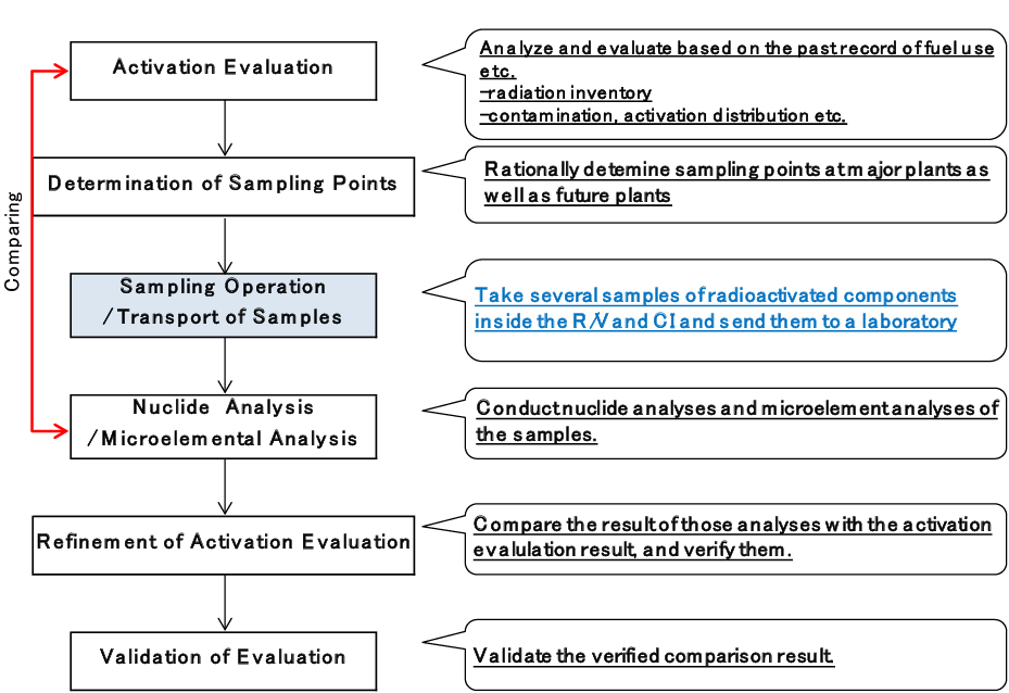
Fig. 1 Verification flow of estimated radioactive concentration
(2) Sampling Points and the Number of Samples
As mentioned above, where to take samples and the number of samples to be taken were determined considering neutron flux and elemental composition which especially affect the activation evaluation. Twelve samples are taken from the reference plant. Afterwards, six samples will be taken from a plant subsequent to the reference plant (hereinafter called a subsequent plant) since its sampling number can be reasonably decreased by utilizing the data from the reference plant. (Fig. 2)
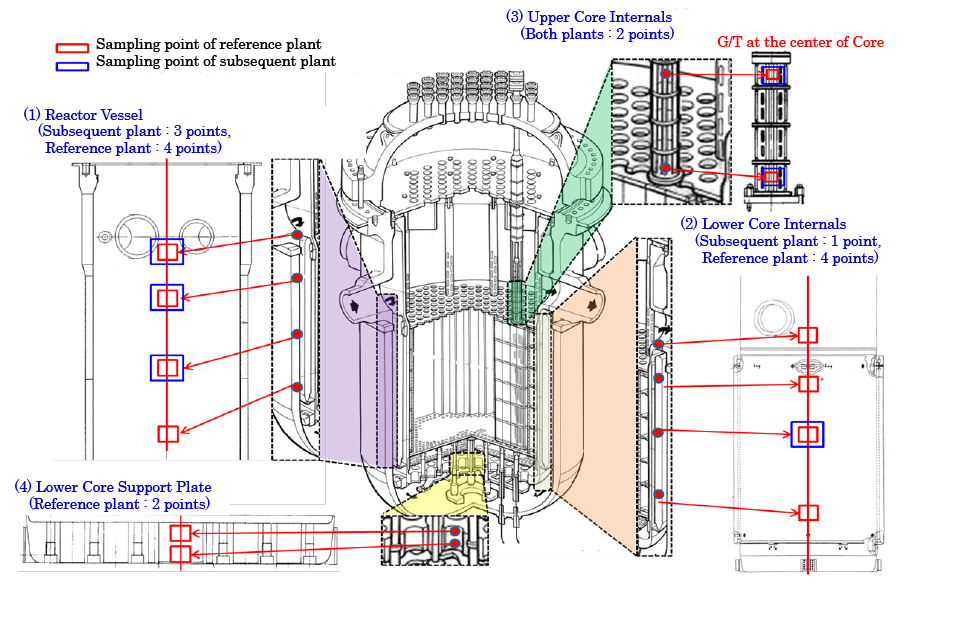
Fig. 2 Sampling Points
(Provided by: Mitsubishi Heavy Industries, Ltd.)
In regard to the sample sizes, each sample has to be more than 10g. Particularly samples from R/V, which is made of low-alloy steel with stainless alloy lining on the surface, they have to be taken from more than 20 mm in depth.
4.2 Overview of Sampling Machine
(1) Selection of Sampling method
A method of electric discharge machining was selected for this sampling task based on the following reasons; (a) able to process remotely and under water for the purpose of radiation exposure reduction, (b) compact in size and low reaction force rather than normal grinding and machining, (c) easy to process complex material since composition of R/V is a mixture of SUS and low-alloy steel, and (d) have a reliable and successful track record in past maintenance tasks. This positioning and handling method has been determined in consideration of workability at the site. As for sampling of R/V, Core Internals and Lower Core Support, a positioning method which utilizes a connecting pole as a tool and adjusts the length of the connecting pole to reach each sampling point was adopted.
(2) Sampling Machine of R/V and Lower Core Internals
A sampling machine of R/V and Lower Core Internals (LCI) and its conceptual positioning diagram is illustrated in Fig.3. This sampling is achieved using two U-shaped electrodes attached to the Machine in a circle, applying the current to both electrodes, and rotating the electrodes 90 degrees (vertically) on the same axis to scoop out a metal piece shaped like a boat. The machine head is compatible between R/V and CI sampling machines. Also, its sampling size can be easily varied by changing the positional relation between the electrodes and the sampling target. The sampling machine is positioned at a target point using connecting poles.
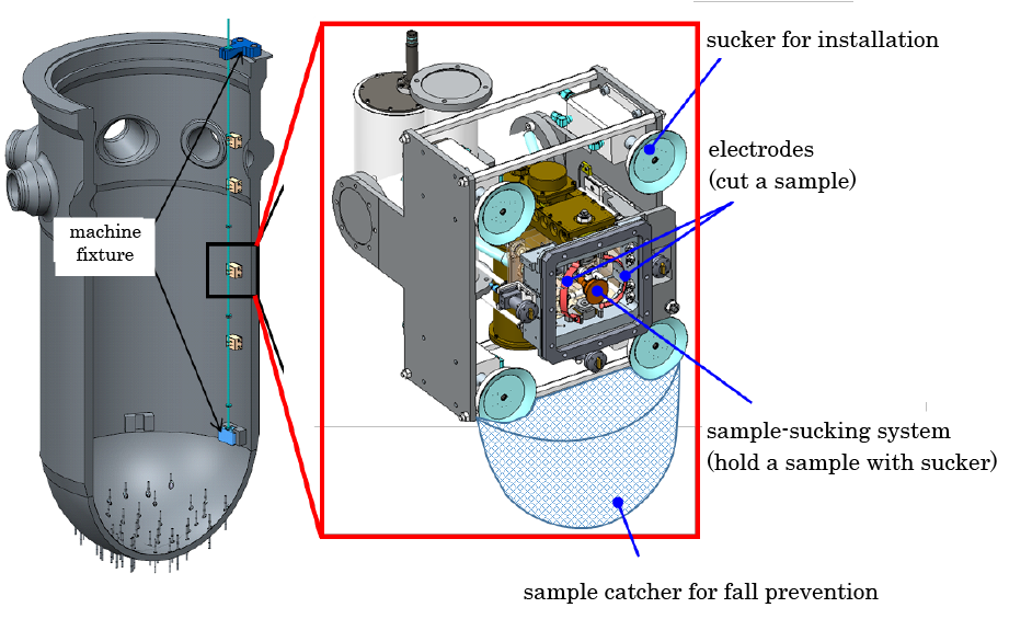
Fig. 3 Conceptual diagram of R/V and CI sampling machine
(Provided by: Mitsubishi Heavy Industries, Ltd.)
(3) Sampling Machine of Upper Core Internal (UCI)
The conceptual sampling diagram of Upper Core Internal (UCI) Guide Tube(G/T) is shown in Fig.4. After removing G/T retaining bolts from UCI, G/T is removed and temporarily stored on a temporary rack (see Fig. 5). From this sampling, cylindrical samples are taken by horizontally cutting out G/T with two parallel electrodes. The sampling machine is transported using the temporary rack on a guide rail, manually lifted with a winch and placed on the designated sampling point.
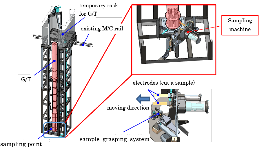
Fig. 4 Conceptual diagram of G/T sampling machine
(Provided by: Mitsubishi Heavy Industries, Ltd.)
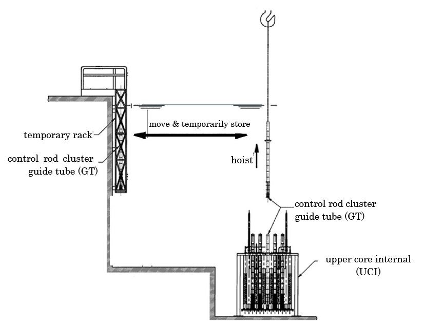
Fig. 5 Procedure of G/T removal from UCI
(Provided by: Mitsubishi Heavy Industries, Ltd.)
(4) Sampling Machine of Lower Core Support Plate
The sampling machine of Lower Core Support Plate (LCSP) is illustrated in Fig. 6. This sampling is conducted by opening a hatch at the center of LCSP to go under LCSP to take samples. The conceptual diagram of installed LCSP sampling machine condition is shown in Fig. 7. This sampling also adopts electrical discharge machining like other sampling machines. With the same electrical discharging mechanism as R/V and LCI sampling machine have, two rotating electrodes cut out a boat-shaped sample. This sampling machine is positioned to the target sampling point using connecting poles and its positioning pins which are inserted into lower core plate holes to stabilize the machine in place.
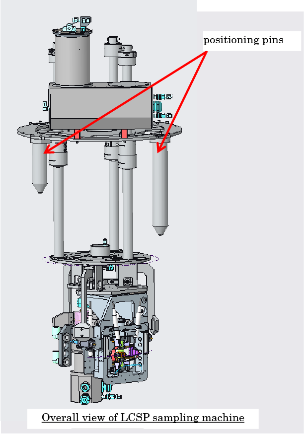
Fig. 6 Illustration of LCSP sampling machine
(Provided by: Mitsubishi Heavy Industries, Ltd.)
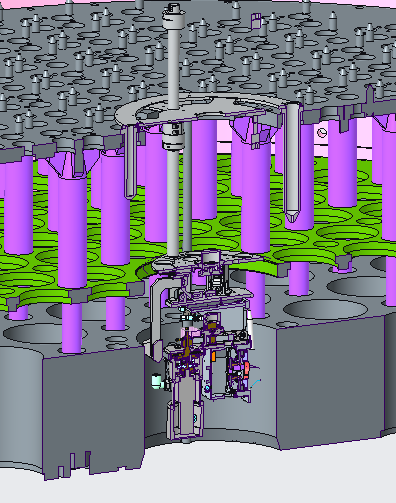
Fig.7 Conceptual diagram of LCSP sampling machine
(Provided by: Mitsubishi Heavy Industries, Ltd.)
5. Example of Application
5.1 Preparation of the Sampling
Prior to the actual sampling work, verification of the sampling machine and a course of the sampling training have been conducted at a site-simulated facility which MHI owns.
Especially in installation of the sampling machines which requires extra careful operation using a more than 10 meter pole while checking underwater cameras, the training using a full-scale mockup was highly effective at site work efficiency as well as damage prevention due to collision between the component and the machine.
Photo 1 shows an actual training scene that a staff member is assembling the sampling machine and the connecting pole using a ceiling crane, and positioning them onto a LCI mockup.
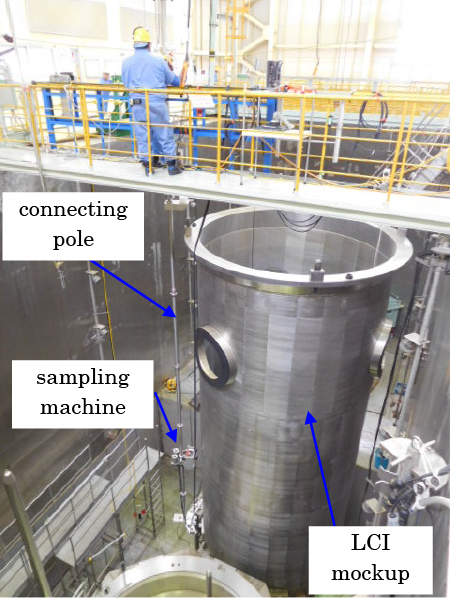
Photo 1 View of training using a mock-up
(Provided by: Mitsubishi Heavy Industries, Ltd.)
5.2 Application on site
Decommissioning of Unit 1 and 2 of Mihama Nuclear Power Plant, owned by Kansai Electric Power Co., Inc. (KEPCO), has been determined in March 2015, and the approval has been given by Nuclear Regulation Authority for the decommissioning plan in April 2017. As the first work in dismantling preparation, system decontamination has been performed and completed in 2017, followed by Unit 2 in September 2018, and Unit 1 in November 2018. R/V sampling of PWR plant during decommissioning operation had never been performed before in Japan and this became the first case within this country (Photo 2).
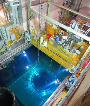
Photo 2 View of sampling on site
(Provided by: Kansai Electric Power Co.)
5.3 The Result of Sampling
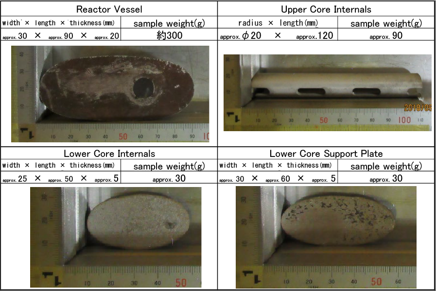
Some of the data from R/V sampling is shown in Table 1. As described in 4.1 (2), 18 ideal-sized samples taken at designated locations were able to be acquired (12 at reference plant, 6 at subsequent plant), which are necessary for accurate evaluation on R/V radiation concentration distribution. After enclosed in a type-A container, these samples were sent to Nuclear Development Corporation (NDC) for detailed analyses.
Table 1 Data of samples (example)
MHI has successfully completed the first PWR R/V sampling work in this country during decommissioning of Mihama Unit 1 and 2. MHI considers this result of analyses which MHI acquired from this sampling work is quite valuable and important for future decommissioning and dismantling planning with consideration for exposure reduction. Subsequently, MHI has accomplished successful sampling and sample shipping at Genkai Unit 1, which is the subsequent plant owned by Kyushu Electric Power Co., Inc.
6. Reference
- 1. a summary of 16th academic lecture meeting, Japan Society of Maintenology “Sampling from Core Internal during PWR Decommissioning” (P.456)
- 2. “Engagement with Safety-first Decommissioning,” from a website of Kyushu Electric Power Co.
7. Contact
Japan Society of Maintenology (ejam@jsm.or.jp)