


Toshiba Energy Systems & Solutions Corporation
Vol. 11, No. 2, NT94
Development of a Maintenance Support Tool
Using Augmented Reality Technology
KEYWORDS:
Maintenance support tool, Augmented reality technology, Visual Simultaneous Localization and Mapping.
1. Technical summary
Classification
6 - C
From the viewpoints of safety plant operation and improvement of utilization rate of equipment, reduction of the human error in inspection work and efficient maintenance engineering and inspection work are needed. Therefore, we developed a maintenance support tool using augmented reality (AR) technology and self-localization technology. The support items, the function and the applied technology are selected based on the information of the sample cases such as inspection error and operation error in maintenance tasks as shown in Fig.1. They can help various inspection works.
AR is the technology to merge a live view of the real world with computer-generated images. A virtual content is superimposed on real image. Typical AR content displayed on the smartphone is shown in Fig.2. AR makes it possible to display information required for inspection on the application screen of a portable devices such as a smart phone or a tablet personal computer (PC). Furthermore, the self-localization technology using Visual Simultaneous Localization and Mapping (Visual SLAM) technology is adopted for navigation to the inspection point.
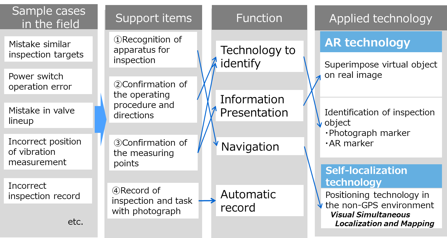
Fig.1 Concept of the remote control system for a sensor-less manipulator
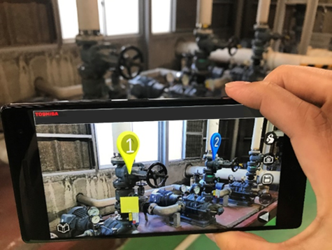
Fig.2 Typical of AR content displayed on the smartphone
2. Development Phase
3. Scope
- (1) Components:
Tablet PC and software for patrol inspection
- (2) Location:
N/A
- (3) Materials:
N/A
- (4) Condition:
N/A
4. Features
AUGMENTED REALITY TECHNOLOGY AND SELF-LOCALIZATION TECHNOLOGY
The AR technology and self-localization technology are adopted in this patrol system. AR is the technology to merge a live view of the real world with computer-generated images. AR makes it possible to display information required for inspection on the screen of a portable device such as a smart phone or a tablet PC. In order to recognize an inspection object and superimpose virtual object on a real image, our system adopted photograph marker and AR marker as a technique to identify inspection target as shown in Fig. 3. This system stores information on AR content associated with each marker. The information includes the positional relationship between the marker and the AR content and the affiliation of the color and shape of the AR content etc. When the marker is recognized, AR content is displayed based on the stored information.
(1)Photograph marker
(2)AR marker
Fig.3 Technique to identify inspection target
Furthermore, we also adopted self-localization technology using Visual Simultaneous Localization and Mapping. This technology estimates a self-position and creates a surrounding map simultaneously using the information obtained by the camera and the depth sensor of the portable device.
The concept of this technology is shown in Fig. 4. The position of the portable device in the three-dimensional coordinate is obtained by computing distance to the characteristic points on surrounding the objects (Object 1 to Object 6) recognized through the pictures (Picture 1 to Picture 3) at every place. As a result, prediction of the position of the portable device and recognition of objects to be inspected can be achieved indoors, while Global Positioning System (GPS) is unavailable. This technology helps inspection worker navigate to inspection point and record inspection data combined with position information.
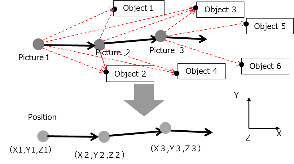
Fig.4 Self-localization method using Visual Simultaneous Localization and Mapping
5. Example of Application
The functional evaluation of the prototype applications was performed in the experimental facility. As a result of use by several experienced inspection workers, it was confirmed that this system could be used for on-site information management and inspection. The following shows each function.
(1) Inspection menu and navigation
In order to do the planned work efficiently and certainly, movement to the inspection point and recognition of equipment for inspection are supported. An application screen of this function is shown in Fig. 5. The order, content and location of the inspection will be displayed in the task list. Each inspection location is also displayed on the inspection point map. Inspection workers are navigated to the inspection point using Visual SLAM technology. This function helps workers confirm inspection items and points before starting inspection.
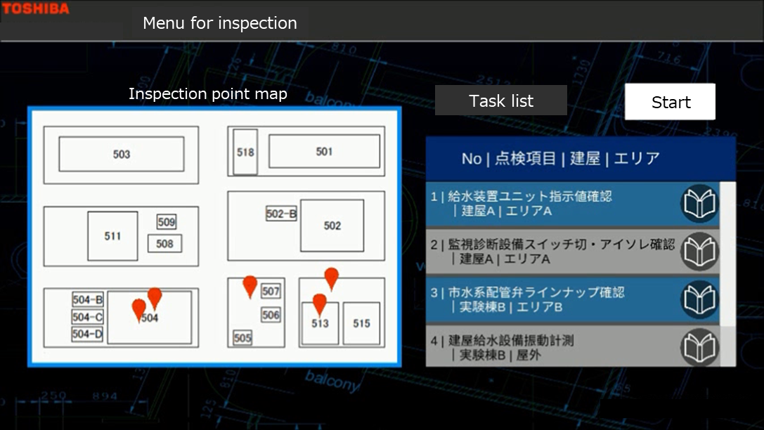
Fig. 5 Typical application screen of inspection menu and map
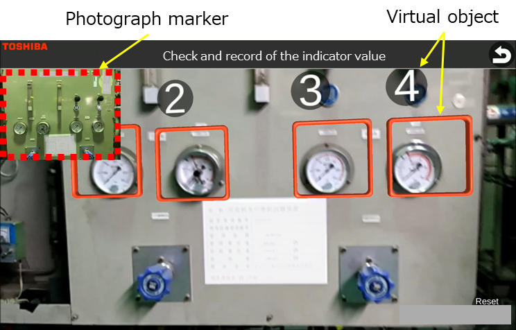
(2) Support of reading instruments
In inspection tasks, reading and recording of numerical values of analog instruments at field sites are carried out. An application screen of this function is shown in Fig. 6. In this sample a photograph of the analog meters obtained beforehand is registered as a photograph marker. Each meter is automatically recognized by using the photograph marker, and frames and numbers are appended by AR to four meters. Workers recognize with these frames and numbers that the tool has grasped the meters to be inspected. It automatically reads values of analog meters from the position of their needles. The value for each meter is displayed on the checklist and is automatically saved when finally checked by the worker. This function helps improve efficiency of the inspection tasks, and reduces human errors as well.
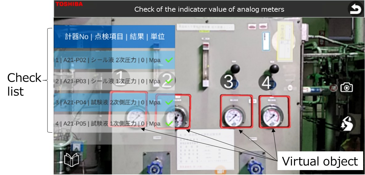
Fig. 6 Support of reading instruments
(3) Support of electrical isolation
Electric isolation is required for some of the checking tasks. The tool supports confirmation of the switches that should be operated to prevent mistakes in power supply operations and improve the efficiency of the task. An application screen of this function is shown in Fig. 7. A photograph of a power supply panel obtained beforehand is used as a photograph marker, and switches to be operated are displayed as virtual objects. The ON / OFF status of each power switch is displayed on the checklist and is automatically saved when finally checked by the worker. The tool enables workers to confirm and record the on/off state of switches.
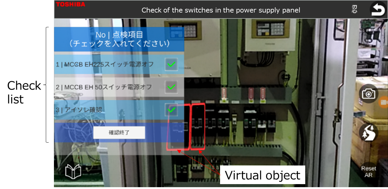
Fig. 7 Support of electrical isolation
(4) Support of valve lineup
This function supports valve lineup tasks, in which workers check the open/close state of each valve at inspections and start-up operations. The tool reads a marker near the object part to be inspected and displays virtual objects arranged in the object based on positional relationship with the AR marker, visualizing the position and the state of the valves. An application screen of this function is shown in Fig. 8. The tool enables workers to confirm and record the open/close state of valves with virtual objects. It is also possible to switch the lineup pattern according to the operation mode.
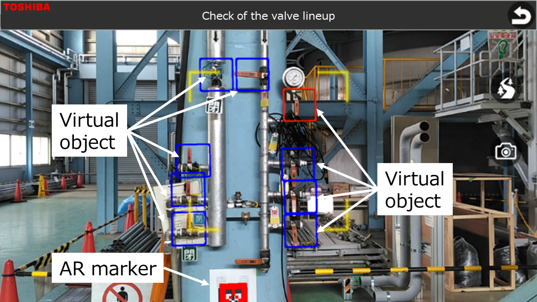
Fig. 8 Support of valve lineup
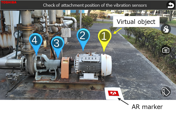
(5) Support of sensor attachment
Vibration measurement for pumps are conducted in periodical inspection. Sensors for measurement usually have to be attached on the position specified according to manuals. An application screen of this function is shown in Fig. 9. The tool recognizes a pump to be inspected by reading the AR marker. The positions where sensors should be attached are displayed as virtual objects, based on the positional relationship to the AR marker.
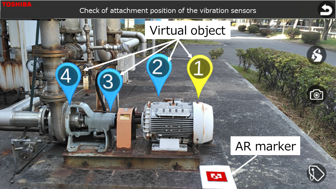
Fig. 9 Support of sensor attachment
(6) Support of maintenance/calibration object confirmation
This function supports confirmation of instruments such as flowmeters to be periodically checked and calibrated. An application screen of this function is shown in Fig. 10. The tool recognizes flowmeters to be checked or calibrated by reading AR marker. The calibration periods of the flowmeters are displayed and classified as virtual objects with different numbers and colors, based on positional relationship with the AR marker. Workers are able to grasp intuitively maintenance plans including flowmeter calibrations by overlaying information on the actual apparatus at the field site.
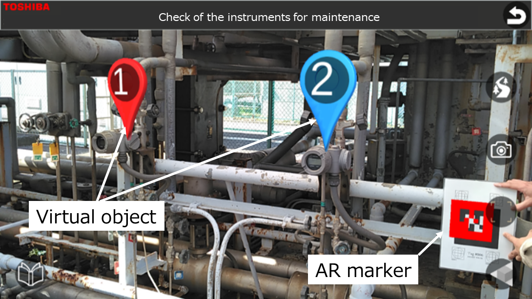
Fig. 10 Support of maintenance/calibration object confirmation
(7) Management of information using virtual tags
Workers occasionally have to record cautions and notices in the field tasks such as inspection and maintenance. While these tasks usually have been controlled with tags at the site, this tool manages them with electronic information. As shown in Fig. 11, virtual tags that contain cautions and notices are attached on the object of interest and displayed on the screen. Since they are recorded with position information, workers are able to easily grasp their positions on a map at next inspection, leading to improve the efficiency of confirmation task as well as the management of states of corrective actions.
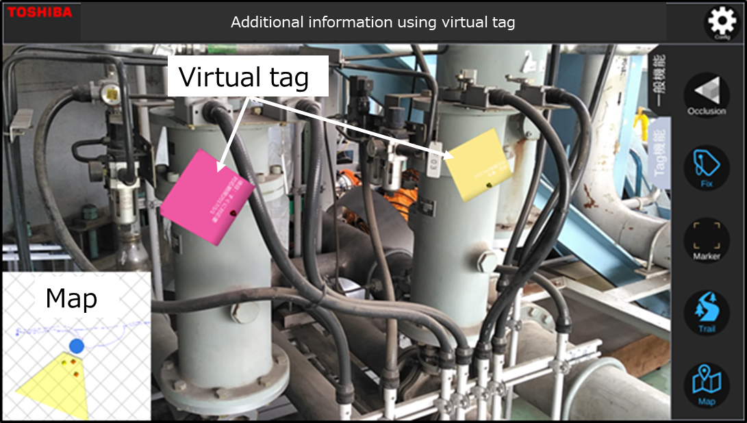
Fig. 11 Management of information using virtual tags
6. Reference
- 1. Jorge F. et al., Visual simultaneous localization and mapping: a survey, Artificial Intelligence Review, Volume 43, pp 55–81, 2012
- 2. Oshima et al., Development of a Maintenance Supporting Tool Using Augmented Reality Technology, 15th Annual Conference of Japan Society of Maintenology, pp311-314, 2018
7. Contact
Japan Society of Maintenology (ejam@jsm.or.jp)