


Mitsubishi Heavy Industries, Ltd.
Nuclear Plant Service Engineering co. ,Ltd.
Vol.10, No.4, NT92
The first FSD due to the measures associated with PWR including SG contains nickel base alloy materials (Inconel 690)
KEYWORDS:
Full System Decontamination (FSD), Decommissioning, PWR, Mihama Unit 1&2
1. Technical summary
Classification
7 - A
Safety countermeasures have been promoting to secure high safety of nuclear power plants after the Great East Japan Earthquake in 2011 and some of power plants have already been restarted. On the other hand, some of power plants have been decided to be decommissioned. MHI has been supporting utilities concerning the project planning of decommissioning of the power plants. One of the work process for the purpose is to reduce radioactivity levels of major system of primary coolant systems in PWR by removing radioactive substances accumulated on the component/piping surface. The process is called as “full system decontamination(FSD)”. The FSD improves the work environment at dismantling phase of the components in the future by reducing radiation exposure dose on workers and reduce radioactive waste.
Kansai Electric Power Co., Inc. (KEPCO) has decided to decommission Mihama Power Plant Unit 1 and 2 in April, 2015 as the Japan’s first decommissioning decision of commercial PWR power plant. MHI calculate the dose equivalent rate on the components, piping etc. in each system in advance and propose to KEPCO that the area to treat FSD should be the reactor coolant system (RCS), the chemical and volume control system (CVCS) and the residual heat removal system (RHRS) because of lots of radioactive substances remained on the inner surface of those systems due to contacting with primary coolant during operation and past investigation of total radiation exposure dose of workers during dismantling of equipment and piping on the basis of the past experience. The FSD area had finally decided by KEPCO (See Fig.1) with targets of decontamination which are that 1) a removal percentage shall be greater than or equal 90% and/or 2) a surface dose equivalent rate of the outer surface of components/piping after the FSD operation shall be less than or equal 0.05mSv/h.
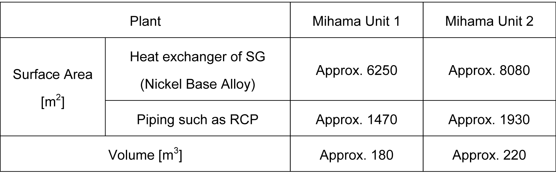
The volume and surface area of the decontamination area of the system calculated based on the drawing etc. of the components and piping in each system are shown in Table 1. The volume of the decontamination area of the system is approximately 200m3 whereas small-scale decontamination operations of the system implemented during the periodical inspection etc. is several m3 levels. Though an addition of large amounts of chemicals is required to secure an enough concentration of the chemicals to implement decontamination operations, chemical decontamination method that used additive or other chemical agent are decomposable is required because additive or other chemical agent may generate secondary wastes. In addition, approximately 80% of surface area to be decontaminated is a nickel base alloy (Inconel 690) and the most of nickel base alloy is used for the heat exchanger tube of steam generator (SG). Nickel base alloy is used for the heat exchanger tube of SG in the domestic plants. To obtain the decontamination effect for the heat exchanger tube of SG is essential for an accomplishment of the decontamination target. On the other hand, however, it was unique in world history in the sense that removing the radioactive contaminants from the SG composed of nickel base alloy.
MHI proposed to KEPCO from the following view point to select the decontamination method to be applied.
- The method that decontamination effect of the heat exchanger tube of SG consisting of nickel base alloy can be expected. ( It is unique in world history.)
- Secondary wastes due to the decontamination operations of the system (derived from additive or chemical agent) shall be less.
- Additive or chemical agent to be used for the decontamination operations of the system can be treated in the power plant.
- The method shall be based on the past experience and a result in the overseas PWR plants.
As the result of pre-review/pre-evaluation and confirmation, MHI proposed CORD method (Chemical Oxidation Reduction Decontamination based on Framatome’s technique* ) to KEPCO which is chemical decontamination method. Joint venture of Marubeni Utility Services, Ltd. and MHI had got the contract of this FSD which is Japan’s first decommissioning of commercial nuclear power plant and implemented/completed the operation in August, 2017 for Mihama unit 1 and in November to December, 2017 for Mihama unit 2.
*Chemical decontamination means that removing the oxide layer (NiFe2O4, NiCr2O4 etc.) formed on the inner surface of the components and piping of the system and the method to reduce the surface dose equivalent rate. Chromium in the oxide layer will be removed by using oxidizing agent and other metals (iron, nickel etc.) including radioactive nuclide will be removed by using reductant agent.
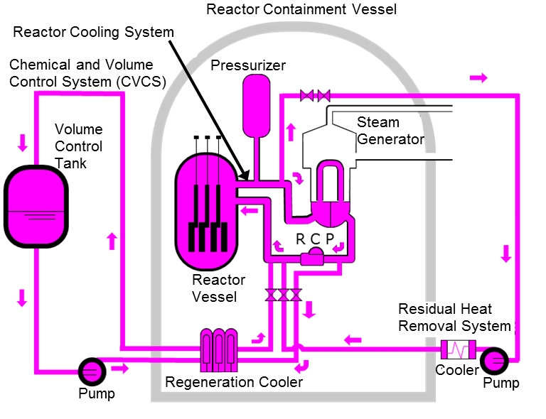
Figure 1 the FSD area
Table 1 Volume and Area in Mihama Unit 1&2
2. Development Phase
3. Scope
- (1) Components:
Decommission
- (2) Location:
Primary system in PWR.
- (3) Materials:
N/A
- (4) Condition:
N/A
4. Features
In the FSD, plant facilities have been effectively utilized for circulation/temperature maintaining of decontamination liquid, pressure control etc. and auxiliary facilities for decontamination operation have been used for chemical injection, decomposition/purifying of decontamination liquid etc. (See Fig.2)
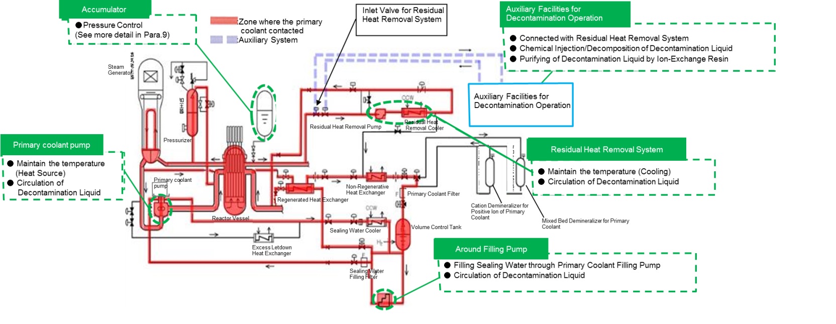
Figure2 Schematic illustration of systems for the FSD in Mihama Unit 1&2
As for the main plant facilities to be used, there are RCP, plant facilities for charging pump, facilities for the residual heat removal system (RHRS), and an accumulator. Primary coolant pump has been used for circulation of heat source/decontamination liquid to maintain the temperature, plant facilities for charging pump have been used for injection of sealing water into primary coolant pump and for circulation of decontamination liquid, facilities for the residual heat removal system (RHRS) have been used for cooling to maintain the temperature and for circulation of decontamination liquid, and an accumulator has been used for a control of the pressure inside the system. Especially, plant facilities for charging pump and an accumulator which were necessary to be modified according to the FSD, connection between plant facilities and auxiliary facilities, and the operation of them have been optimized based on plant supplier’s experience. Its details are shown below.
(1) Pressure control by accumulator
[Usual] (See in Fig. 3)
- Pressure of systems is controlled by pressurizer during normal operation.
[Problem] (See in Fig. 3)
- Pressurizer cannot be used for pressure control because it is also the object to be decontaminated during decontamination operation and it is necessary to be filled with water.
- Though the pressure can be controlled by using Chemical and Volume Control System (CVCS), following problems appear by supply and drainage of water.
→ Pressure rise (Drainage is necessary)
Contaminated area will be expanded due to the drainage of contaminated liquid containing chemicals.
→ Pressure drop (Water supply is necessary)
Secondary wastes will be generated due to the reduction of chemical concentration and additional chemical injection.
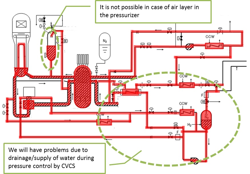
Figure3 Problem of pressure control
[Improvement] (See in Fig. 4)
- An accumulator is used as a buffer tank to keep a storage space capable of storing a primary liquid in the system temporarily due to volume expansion. In addition, the accumulator is implemented some modifications such as addition of pressure adjustment function by automatic pressure regulating valve, addition of uniform pressure line, modification of pressure monitoring setting value to control a pressure by accumulator.
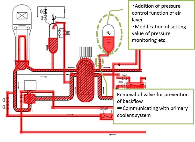
Figure4 Improvement of pressure control
(2)Operation of filling line due to filling of sealing water RCP No.1
[Usual] (See in Fig. 5)
- Filling line of Chemical and Volume Control System is branched to return line to the loop and filling line of RCP sealing water after passing through charging pump during normal operation.
[Problem] (See in Fig. 5)
- The crystal grains which are resulted from chemical reaction and oxide layer are formed in the primary coolant in the system and it may be cause of malfunction of RCP operation during decontamination operation.
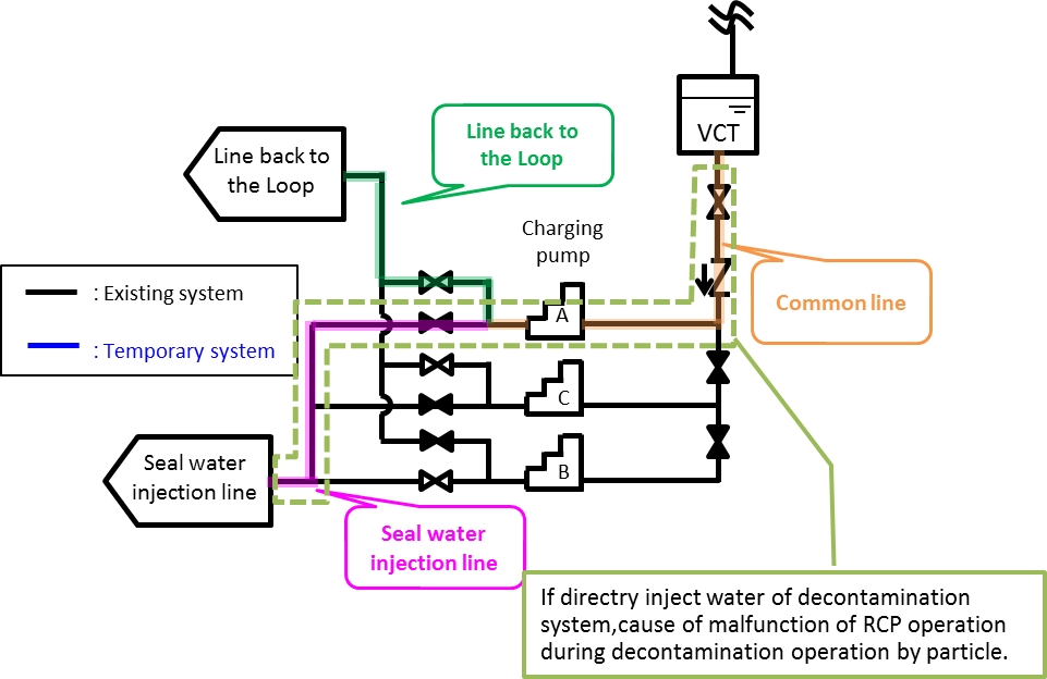
Figure5 Problem of seal water injection
[Improvement] (See in Fig. 6)
- A-charging pump is used for the return line to the loop
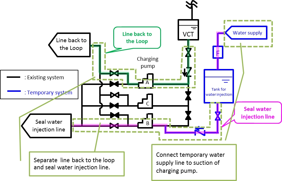
Figure6 Improvement of seal water injection
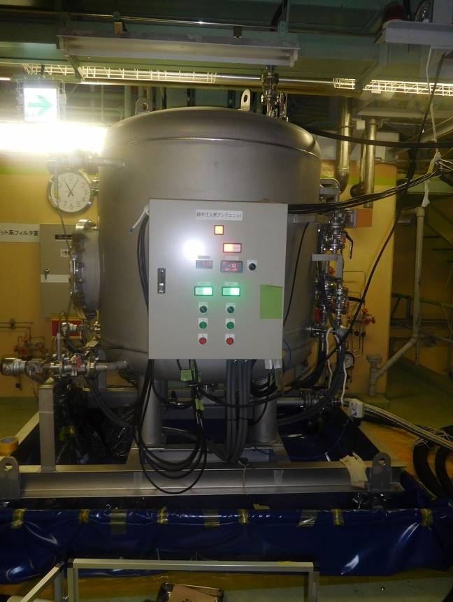
Figure7 Temporary tank for RCP seal water injection
(3) Connection with the auxiliary facilities for decontamination and its operation
The main auxiliary facilities for decontamination is AMDA (Automated Modular/Mobile Decontamination Appliance) manufactured by Framatome (See Fig.8) and AMDA was transported to Japan from Europe for FSD. It is composed of a plurality of devices such as pressure reducing device (decompression unit), tank, pump etc. This facility has functions such as filling of chemicals, decomposition / purifying of decontamination liquid, sampling of decontamination liquid. AMDA is connected with plant facilities through the valve of the RHRS. Operational actions have been implemented while always keeping contact with the operator of plant facility/auxiliary facilities because operation of plant facility may be adversely affected due to filling of chemicals etc. and lead to increasing of pressure in the plant facility side. Devices composed of AMDA have been basically installed in an operation floor in the reactor containment vessel and ion-exchange resin column which has high radiation dose rate have been installed directly on the bottom part of the reactor containment vessel so as to minimize workers' exposure and the dose of direct radiation and the sky-shine radiation are taken into account. (See Fig.9)
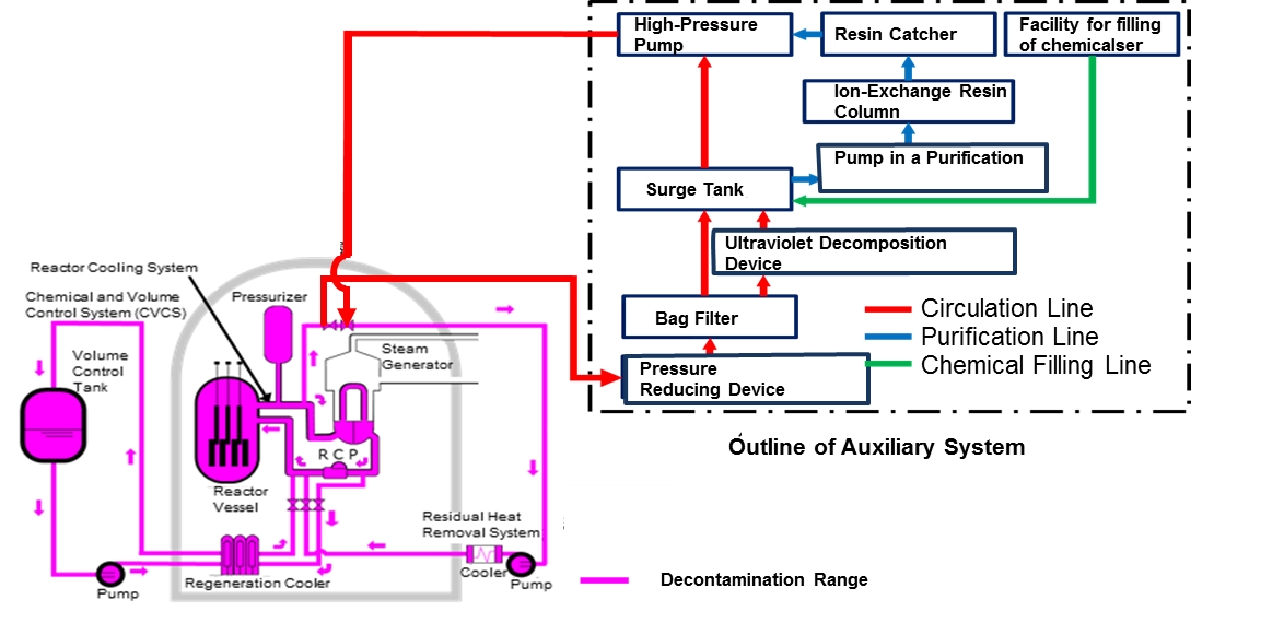
Figure8 Schematic illustration of auxiliary systems(AMDA)
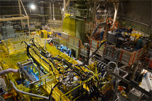
Figure9 View of auxiliary systems for the FSD in Mihama1 Unit 1
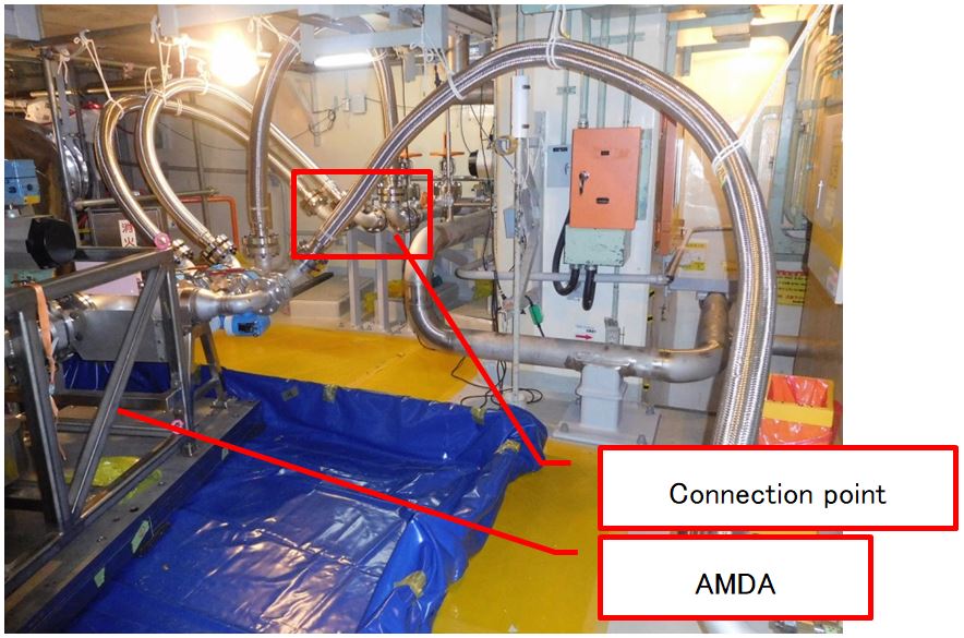
Figure10 Connection point to RHRS from AMDA
*This picture shows an operation floor in the reactor containment vessel, and ion- exchange resin column is not in this picture due to high radiation.
5. Example of Application
MHI will introduce the results of the operation for the FSD due to the measures associated with decommissioning of reactors in Mihama unit 1 and 2 by utilizing facilities and operations introduced in paragraph 4. In addition, 2 phase trial operations have been performed prior to start actual the FSD, one is single trial operation for each facility and the other is integrated trial operation which is each facility has been connected same as actual decontamination operation. MHI performed actual decontamination operation with the best condition after confirming the no leakage from the joint portion of the facilities without any malfunction in these trial operations. Flow diagram of facilities before starting of decontamination operation is shown in Fig.11.
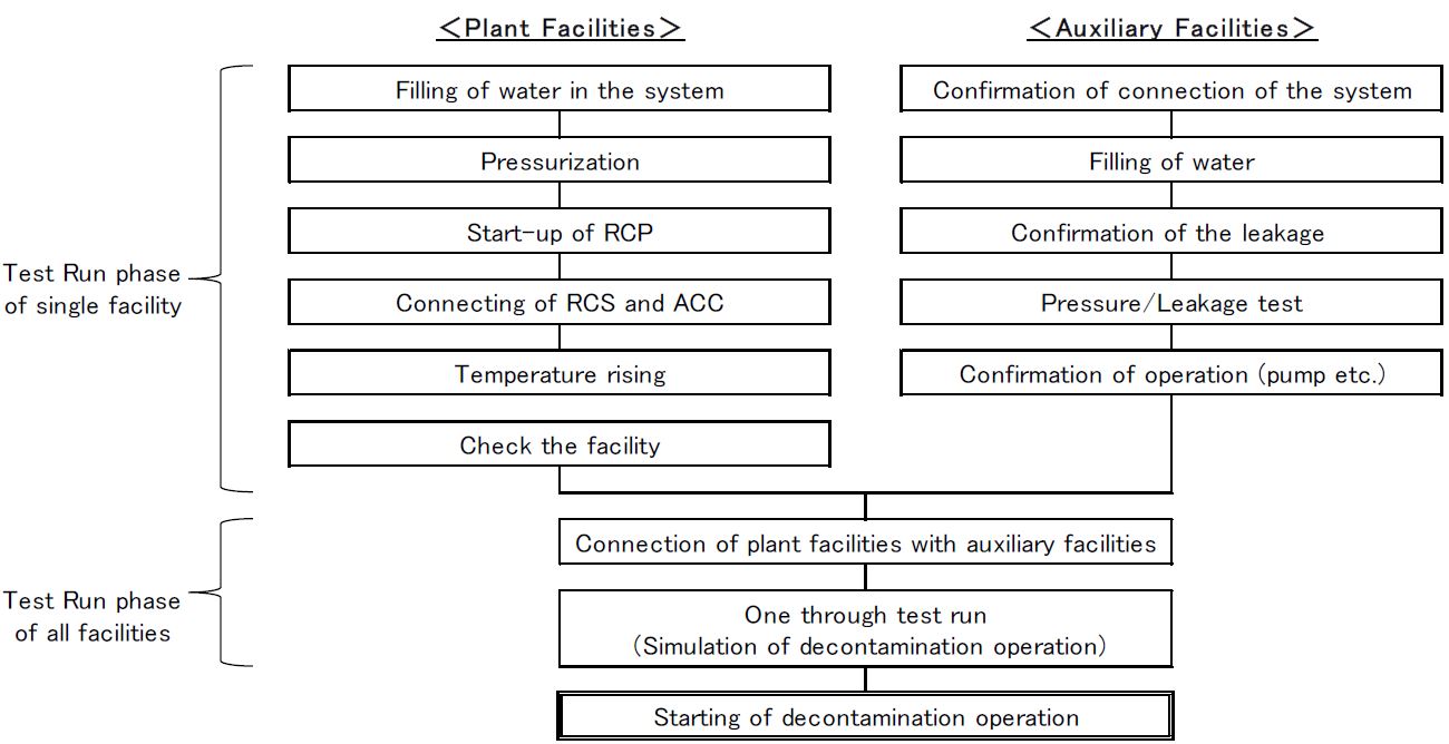
Figure11 Starting up flow of systems
Of course, it is necessary to control the operations of plant facilities/auxiliary facilities shown in paragraph 4 and it is also necessary to control chemical decontamination process simultaneously that changes in accordance with the analysis result of system water sampling at the site operation. And we has implemented/completed decontamination operation for both Mihama unit 1 and 2 without any trouble, accident.
MHI achieved a surface dose equivalent rate of less than or equal 0.05mSv/h for the outer surface of primary coolant system piping etc. after decontamination operation which are made by stainless steel and a surface dose equivalent rate is comparatively low before decontamination operation, and MHI achieved decontamination factor after decontamination operation which is far beyond the decontamination target for heat exchanger tube of SG which is made by nickel base alloy and have 80 % of total surface area.
Table2 Decontamination factor & dose equivalent rate in Mihama Unit 1&2
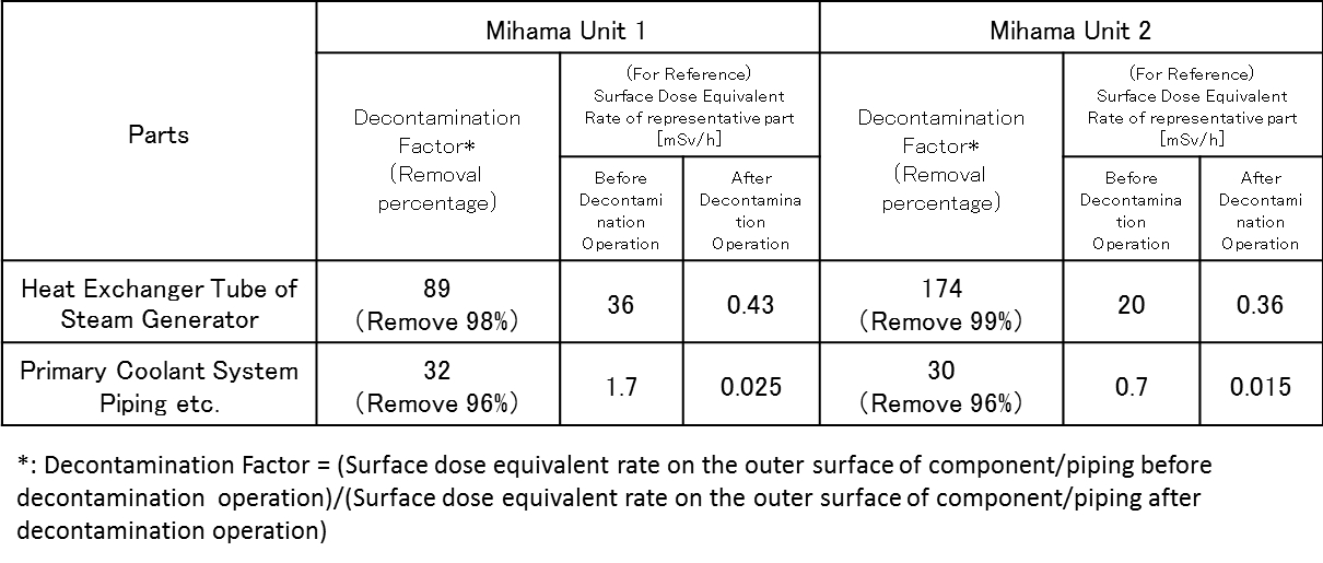
Surface dose equivalent rate of Mihama unit 1 and 2 have been reduced totally by this FSD and especially, MHI could reduce surface dose equivalent rate of double-digit decrease for heat exchanger tube of SG before/after this FSD. Consequently, substantial improvement for the work environment during the operations associated with decommissioning of reactors in the future (minimize workers' exposure, reduce the risk of internal exposure of workers due to suction of radioactive dust of inside the facility being dismantled), and reducing the radioactive level of the radioactive waste can be highly expected.
MHI will optimize future study of the FSD in Japan based on this experience.
6. Reference
- 1.https://www.kepco.co.jp/energy_supply/supply/ichiisenshin/thought/interview14.html
7. Contact
Japan Society of Maintenology (ejam@jsm.or.jp)