


Hitachi-GE Nuclear Energy, Ltd.
The Japan Atomic Power Company
Vol.9, No.2, NT85
Water Jet Peening Technology for BWR internals on cracked surface
KEYWORDS:
Water Jet Peening, Stress Corrosion Cracking, Crack Initiation, Crack Propagation
1. Technical summary
Classification
5 - B (Improvement)
Water Jet Peening (WJP) has been widely applied to Japanese nuclear power plants since 1999 in order to mitigate Stress Corrosion Cracking (SCC) initiation on SCC sensitized material used in their reactors as an approved mechanical mitigation technique against SCC [1][2]. WJP has been applied to non-cracked reactor internals as a preventive maintenance method in most cases. However WJP can be apply to cracked surface to mitigate initiation of any additional SCCs.
WJP is a kind of peening methods using cavitations and is known as one of the most successful underwater peening methods to the reactor internals in BWRs (Boiling Water Reactors) and PWRs (Pressurized Water Reactors) in Japan. It is known that causes of SCC are categorized into three factors; aggressive environment, sensitized material and tensile stress. SCC can potentially be mitigated by removing or reducing at least one of the three. WJP reduces residual tensile stress and puts the surface and near-surface layer in high compression to mitigate SCC potential [1].
Laboratory data shows that WJP has an effect to mitigate or suppress shallow crack propagation if the achieved compression depth is deeper than the crack. WJP has no adverse effect on pre-existing cracks on the mitigated surface, such as crack propagation during WJP treatment or acceleration effect after its treatment [3]. However, there was no field experience applying WJP to cracked surfaces of operating reactor internals. Since removing the crack(s) is practice in Japan, the crack(s) is removed prior to WJP implementation.
In 2005, SCCs were found on shroud support V8-OD weld joints in the Tokai-2 reactor. In 2009, an additional 38 SCCs were found on V8-ID and H7-ID weld joints shown in Fig.1. H7 and V8 weld joints are made of Nickel based Alloy 182. These cracks were evaluated and left as is with the requirement that they should be inspected for crack sizing with Ultrasonic Testing (UT) periodically to monitor each crack propagation according to the regulator’s direction. In order to mitigate initiation of any additional SCCs on non-cracked area and area between the cracks, WJP was considered as an applicable candidate.

Fig.1 Locations Of H7 and V8 weld joints in Tokai-2 reactor
(H7 and V8 Weld joints: Nickel based Alloy 182)
2. Development Phase
3. Scope
- (1) Components:
BWR and PWR internals
- (2) Location:
Weld joint
- (3) Materials:
Nickeled based alloy and stainless steel
- (4) Condition:
Under water
4. Features
- (1)No significant difference in the UT sizing data before and after WJP treatment
-
As stated earlier, when observed cracks are left as is, it is required to perform the crack sizing periodically by UT in order to monitor its propagation. In order to apply WJP to the cracked surface, it is necessary to clarify that no adverse effect on UT sizing capability after WJP should be observed. UT sizing test on SCC initiated material was performed before and after WJP[4].
SCCs were initiated by three-point bending in potassium tetrathionate solution. Test pieces were made of 304S.S. and Nickel based Alloy 182. WJP was applied in two directions; one is parallel to the crack and another perpendicular to the crack in order to simulate the actual treatment condition. Other treatment conditions are selected conservatively. Phased array UT from cracked surface was performed after 7 to 8 points for UT sizing on the target SCC was selected. The Points for UT sizing were the same before and after WJP. After all UT scans were performed, the echo levels and images, before and after WJP, were compared. Thereafter, comparison of measured crack depths, before and after WJP, is performed.
Test results showed that there was no significant difference in UT crack sizing data before and after WJP as shown in Fig.2 and Table 1. With these results, WJP has no adverse effect on UT sizing capability.
- (2)Tensile stress mitigation on cracked surface
-
Although inspection relief cannot be obtained by applying a surface stress improvement process on cracked surfaces, it is still preferred to mitigate additional crack initiation on the cracked area. WJP can mitigate the tensile stress on the cracked area [4]. The residual stress measurements, near and between the cracks, were performed before and after WJP.
Test pieces were made of 304S.S. and Nickel based Alloy 182 with thermal treatment as well as machining before crack addition, in order to simulate actual material conditions. For SCC initiation on each test piece, which simulates a surface with single SCC, three-point bending process in potassium tetrathionate solution was used as shown in Fig.3 and Fig.4. Target pre-crack depth was 10mm, which is deep enough compared to stress improvement depth with WJP. On the other hand, four slits which simulated SCCs were prepared by Electro-Discharge Machining in order to control gaps between cracks as showed in Fig.5. These gaps between cracks were 3mm, 5mm and 10mm.
After crack addition onto the test pieces, surface finish with heavy grinding has been performed in order to add tensile residual stress on the cracked surface. Thereafter, initial residual stress of the test pieces with single SCC was measured on the surface. 100 & 200 micrometers subsurfaces by X-ray Diffraction method (XRD), and initial residual stress of the test pieces with four slits was measured on the surface by XRD. After initial residual stress measurement, WJP was applied to these test pieces and the direction was perpendicular to the crack. In this test, the weakest WJP condition was selected conservatively. After WJP treatment on each test piece, residual stress was measured on the surface 100 & 200 micrometers subsurfaces by XRD.
The evaluation of compressive residual stress level near a crack and between cracks is shown in Fig.3, 4 and 5. It is observed that there is no adverse effect, such as tensile stress addition, close to the crack. Compressive stress could be achieved to a depth of 200 micrometers at all of the measured points. Therefore, WJP is effective on cracked surfaces and mitigates SCC potential with its surface stress improvement capability close to, and between cracks.
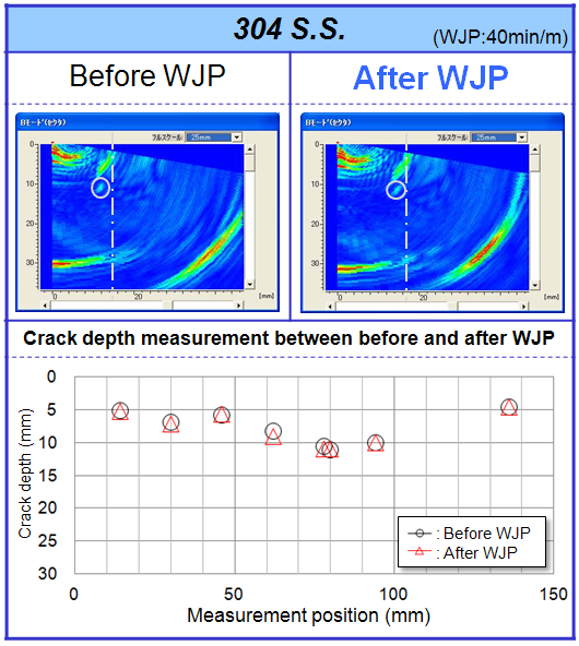
a) Test piece: 304S.S.
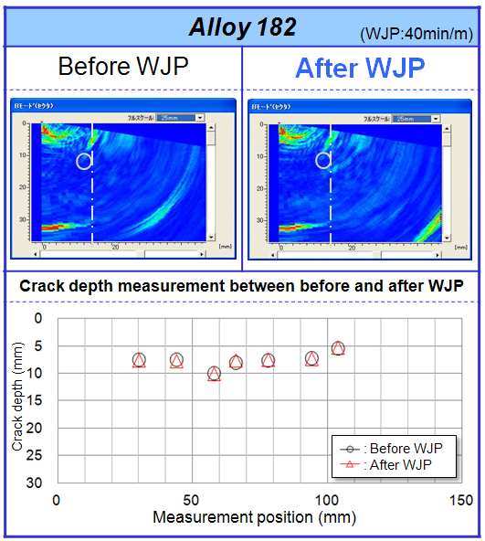
b) Test piece: Nickel based Alloy 182
Fig.2 UT results before and after WJP
Table 1 Mean Error of sizing difference*1 before and after WJP
| Material | Mean Error(mm) | Sample size |
| 304S.S. | 0.06 | 64 |
| Alloy 182 | -0.01 | 30 |
*1: Subtracted data after WJP from data before WJP

a)Specimen outline(SCC on 304S.S)
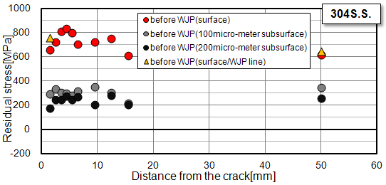
b)Residual stress on initial data line
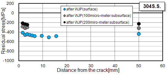
c)Residual stress on WJP line
Fig.3 Residual stress near the crack(304S.S)

a)Specimen outline(SCC on Alloy182)
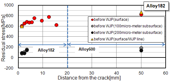
b)Residual stress on initial data line
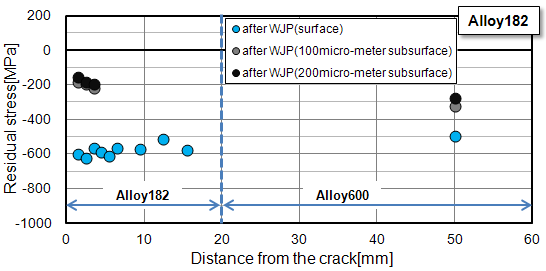
c)Residual stress on WJP line
Fig.4 Residual stress near the crack(Alloy182)

a)Specimen outline
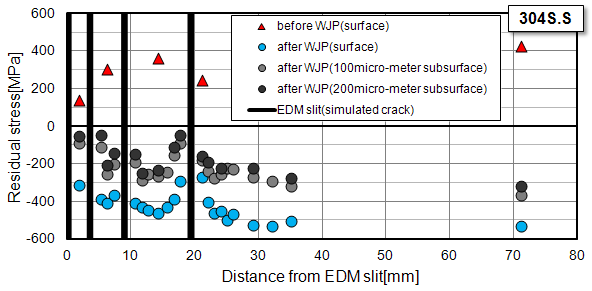
b)XRD measurement result
Fig.5 Residual stress between cracks
5. Examples of Application
As stated earlier, WJP has no adverse effect on cracks surface. WJP field implementation on H7/V8-ID in the Tokai-2 reactor has been performed in five days in 2011[6]. As shown in Fig.6, Visual Test (VT) showed that there was no visible difference before and after WJP.

Fig.6 Cracked surface before and after WJP in Tokai-2 Reactor
6. Reference
- 1. E-JAM Vol.1, No.2, NT-7
(Water Jet Peening Technology for Preventing Stress Corrosion Cracking by Using Cavitations) - 2. M. Fukaya et al, 2011, “Prediction of Residual Stress Improvement by Water Jet Peening (WJP) Using Cavitating Jet and Residual Stress Simulations”, ICONE19-43877, ASME 19th Int. Conf. On Nuclear Engineering (ICONE19), ASME, New York
- 3. Hirano K, et al.: Effects of Water Jet Peening on Corrosion Resistance and Fatigue Strength of Type 304 Stainless Steel, Journal of the society of materials science Japan vol.45, No.7 (1996.7)
- 4.Ren, M, et al. , 2012, “Application of Water Jet Peening on Pre-cracked Nickel Based Alloy and Stainless Steel”, PVP2012-78824, Proceedings of the ASME 2012 Pressure Vessels & Piping Division Conference (PVP2012), ASME, New York
- 5. T. Fujino, et al. , 2013, “Crack Growth Behavior and Preventive Maintenance for Reactor Internals with Cracks in Tokai-2 Nuclear Power Plant”, PVP2013-97257, Proceedings of the ASME 2013 Pressure Vessels & Piping Division Conference (PVP2013), ASME, Paris, France
7. Contact
Japan Society of Maintenology (ejam@jsm.or.jp)