


Tokyo Electric Power Company Holdings Inc.,
Hitachi-GE Nuclear Energy, LTD.,
Toshiba Corporation
Vol.8, No.4, NT82
Development of the Eddy Current Testing (ECT) technique for the Feedwater nozzles of Nuclear Power Plant Reactor Pressure Vessels.
KEYWORDS:
Eddy Current Testing, Flaw detection, Plant life extension, Reactor Pressure Vessel, Feedwater nozzle
1. Technical summary
Classification
1 - A
• All Nuclear Power Plants (NPPs) in Japan were limited to an operation period up to 40 years, based on Nuclear Regulatory Authority (NRA) Japan revision to the “Act on the Regulation of Nuclear Source Material, Nuclear Fuel Material and Reactors” in July 2013. In order to operate for more than 40 years, special inspection are needed based on the “Guide for the license application of extension of operation period of Nuclear Power Plant” legislated by NRA. The inspection by ECT for inside surface of Feedwater nozzles to detect fatigue flaws is one of the requirements in the special inspection. The background of this requirement lies in operating experience where there were some thermal fatigue flaws that were several millimeter deep on the surface of the Feedwater nozzles in some domestic plants. The cladding for the nozzle surface was removed or not installed during construction at most domestic BWR plants as one countermeasure for the flaw.
The Reactor vessel material including Feedwater nozzles is Low Alloy Steel (LAS), it is not included in the current “Guide for ECT of Nuclear Power Plant components” (JEAG4217-2010). Two cases of ECT inspection for the Feedwater nozzle were confirmed by the documentation research (includes domestic and overseas).
- 1) The Special Inspection for the Life Extension of Takahama Units 1 and 2, Kansai Electric Power Company [1]
- 2) Special NDT applied to the In-service Inspection of the RPV nozzle and safe-end welds in a BWR plant in the Netherlands [2]
All Nuclear Power Plants (NPPs) in Japan were limited to an operation period up to 40 years, based on Nuclear Regulatory Authority (NRA) Japan revision to the “Act on the Regulation of Nuclear Source Material, Nuclear Fuel Material and Reactors” in July 2013. In order to operate for more than 40 years, special inspection are needed based on the “Guide for the license application of extension of operation period of Nuclear Power Plant” legislated by NRA. The inspection by ECT for inside surface of Feedwater nozzles to detect fatigue flaws is one of the requirements in the special inspection. The background of this requirement lies in operating experience where there were some thermal fatigue flaws that were several millimeter deep on the surface of the Feedwater nozzles in some domestic plants. The cladding for the nozzle surface was removed or not installed during construction at most domestic BWR plants as one countermeasure for the flaw.
These two cases, listed above, had ECT performed on the nozzles with stainless cladding. There were no previous cases that performed ECT to the nozzle corner base metal material made from ferromagnetic material.
To test this configuration, simulated models of Feedwater nozzles flaw detectability and conditions of LAS ECT verification and evaluation have been completed. This simulation, verified the ability to detect the flaw with greater than 1mm depth. The result was reported at the scientific lecture of Japan Society of Maintenology. Details of the finding are this report [3]
This result is to be base-lined for updating JEAG4217.

Fig.1 Reactor Pressure Vessel (BWR) Fig.2 Feedwater nozzle(BWR)
2. Development Phase
3. Scope
- (1) Components: Vessel
- (2) Location:
Nozzle corner base metal, cladding
- (3) Materials: N/ALow alloy steel, stainless cladding
- (4) Condition: Under water
- (5) Others: ECT technique confirmation
4. Features
- (1)Issues of ECT application to Feedwater nozzle
- There are some issues, listed below, that apply ECT of Feedwater nozzle. There is not any verification or baseline information, from previous testing, for ECT to the same material and geometry as the Feedwater nozzle
- ⅰ) Flaw detectability of Feedwater nozzle material
- The Feedwater nozzles are made from LAS (SFVQ1A, SFVQ2A, etc.) which are magnetic materials. In some plants there is surface stainless steel cladding inside surface of the nozzle. Since the permeability of magnetic materials is higher than non-magnetic material, the skin depth permeating eddy currents is small when ECT is applied to magnetic materials. Compared to the non-magnetic material, the higher the magnetic material permeability, as shown below ECT "Skin depth" is reduced indicating an excessive current intensity on the material surface depth in the test, a large tendency for over-current is concentrated on the surface, CT Application of the test is considered difficult.
- In the mathematical formula (1) skin depth (δ) becomes smaller with increasing material conductance (σ) and magnetic permeability (μ) [2]. The frequency (f) does not material dependent.
 (1)
(1)- Generally, flaw detection in the magnetic materials are difficult due to a low SN ratio caused by widely varying magnetic characteristic compared with non-magnetic materials.
- ii) Flaw detectability depends on the shape and configuration
- A typical BWR Feedwater nozzle is shown in Fig.2. Some issues for ECT applications to the corner of the nozzle are listed below
-
- >Shape (combination of curved surface)
- >Surface roughness
- >Effect of the oxide film
- >Relationship of the direction of scanning and flaw length direction
- >Existence of surface cladding
- (2)ECT verification of detectability for Feedwater nozzle corner
- i)Probes and frequency used in the verification test Probes used in this verification test were equivalent to the probes which were used in the past verification test [5] or used in the procedure of JEAG4217. In addition, uniformization probe was used for comparative study. All probes used in this verification test are listed in Table 1
-
Table 1 List of probes in this verification

-
The ECT calibration procedure using a TR Pancake probe was revised as described in JEAG4217 as follows.
The ECT detection using the TR pancake probe was carried out in the combination V detection mode which located an excitation coil and a detection coil in the same direction along longitudinal direction of probe and the H detection mode which located an excitation coil and a detection coil to overlap. In this verification test, the calibration procedure was applied that it could be completed with V detection mode and H direction mode in one scan as shown in Fig.3 to apply the technique to calibrate the V detection mode and H detection mode in a single probe scanning against artificial flaws. This revision of the procedure utilized the characteristic of magnetic materials that detect signal of H detection mode for the orthogonal flaw. -


Fig.3 Probe scan direction of the TR Pancake calibration in this verification test
- ii)Specimens of this verification test
-
Considering the issues shown in 4.(1), the specimens with simulation flaw that simulates actual plants Feedwater nozzle and other shapes to compare were adapted to verify the ECT detectability.
-
The specimen's material were SFVQ1A as a representative of actual plants LAS material, SFVQ1A , SFVQ2A and , ASME LAS material equivalent to JIS material and it was identified on the specimens for calibration that the difference of these materials did not affect the detectability. -
The shape of the specimens consisted of a combination of curves in 3-dimensions that simulated the actual Feedwater nozzles. Although the size and curvature of the each part of the nozzle varied by plant, the inner diameter and corner curvature of the specimens were adopted minimum dimension of actual Feedwater nozzles, 247mm inner diameter and 35mm corner curvature considering the difficulty of tracking the shape. Additionally flat and 2-dimension specimens were used for confirmation of the detectability. -
Considering the issues shown in 4.(1), the simulation flaw was a both mechanical and thermal fatigue flaw. EDM notching was also adopted to compare the detectability. The dimension of these flaw was 1 mm in depth that verified the detectability by ECT in the preceding research [5] and applied as a simulation flaw depth of reference test block in JEAG4217, and indeed 0.5~5 mm was adopted for the flaw depth on the specimens as shown in table 2. The length of the simulated flaw was 11.8 mm for the radius 35 mm curvature arc was compared, using flaw depth up to 1 mm, with 8.4~26.6 mm flaw length on the specimens as shown in table 2.
-
The direction of the simulated flaw was axial with the nozzle and was spread by the comparatively bigger circumferential stress, and circumferential flaw was spread by the axial stress and compared it with precedent cases. -
Although the stainless cladding inside surface of the Feedwater nozzle was removed or not installed as the countermeasure of the thermal fatigue in many BWR plants, a few plants remains the cladding. Because of that the specimens both with and without cladding were used. The surface of the specimens without cladding were machined and polished to be same level condition as the actual plant, and installed oxide film on it. -
The specification of the test specimens is shown in table 2 and pictures are shown in Fig. 4.
- Table 2 Specification of the specimens

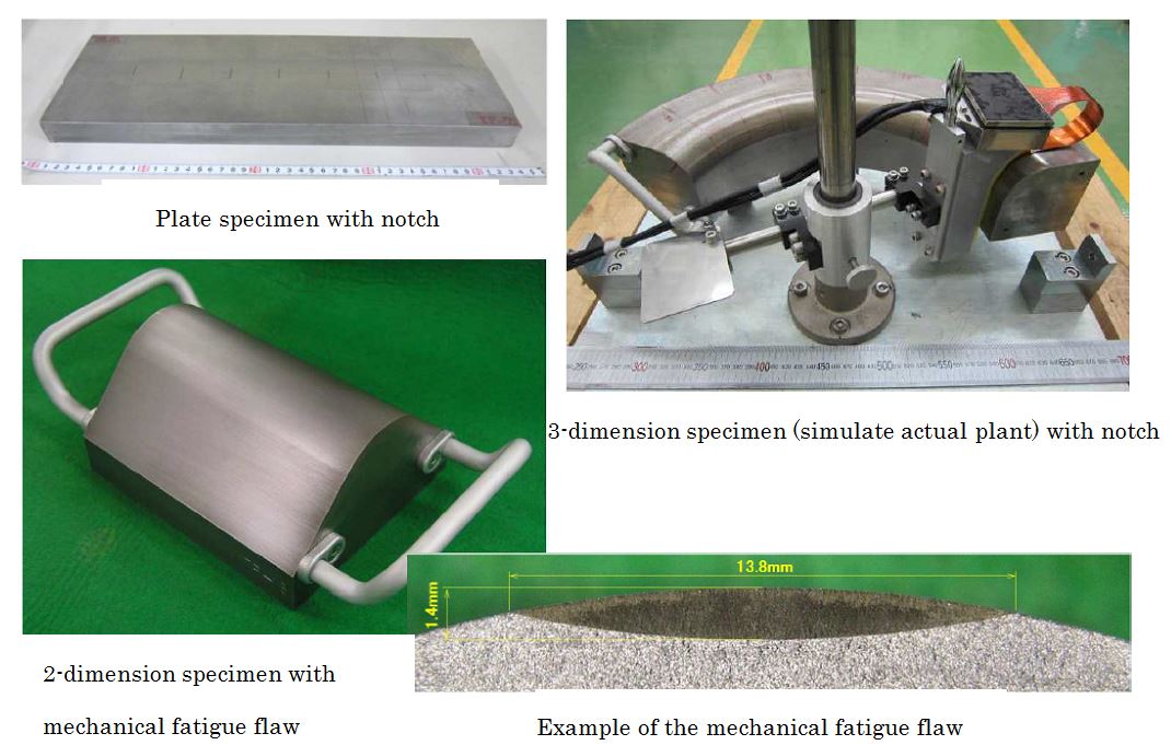
- Fig.4 Pictures of the specimens
- iii)ECT verification test procedure
-
The verification test procedure was based on the contents of JEAG4217, and implemented utilizing combination of multiple ECT systems and frequencies in the air.
In the verification test of plate specimens, the subjects as follows were confirmed.- >Influence of surface condition ( existence of cladding, roughness and oxide film)
- >Relationship of flaw depth and signal strength
- >Comparing of detected signals between EDM notch and fatigue flaw.
- >Effect of noise reduction for magnetic material.
In the 2-dimension specimens, the subjects as follows were confirmed.
- >Influence of corner curvature
- >Relationship of flaw depth and signal strength
- >Comparing of detected signals between EDM notch and fatigue flaw
- >Influence of the flaw direction
In the 3-dimension specimens, the subjects as follows were confirmed.
- >Influence of the shape of Feedwater nozzle of actual plants
- >Influence of surface condition ( existence of cladding, roughness and oxide film)
- iv)ECT verification test result
-
The test results of the flaw detectability of the all probes on all type specimens (plates, 2-dimension and 3-dimension) are shown in table 3, Fig.5-1 and Fig.5-2.
Although some results of specimens without cladding and with above 1 mm flaw were below the reference sensitivity as shown in Table 3 and Fig.5-1, all results of detected signals exceeded the threshold (20% of reference sensitivity) in both EDM notch and fatigue flaw in all specimens and frequencies. Some results of detected signals in the specimens with 0.5 mm flaw and with cladding and 1mm fatigue flaw were below the threshold or no signal. However all signals except for the non-uniformization probe were above the threshold and even in the case of the uniformization probe, a signal applying a scanning 45 degree angle to the flaw was above the threshold.
The C-scope detected images of 1.4 mm depth fatigue flaw are shown in Fig.5-2 as an example. The detectability by all combination of probes and frequencies were identified by these images.
Regarding the surface condition, results of plate specimen with cladding by some probes indicated a low level of detectability. Among these results, the detectability by using TR pancake probe was clearly confirmed by considering the combination the direction of scanning and detection mode, therefore cladding is electromagnetic characteristic of non-magnetic material. (Only the lowest detection results were listed as representative of results in table 3) Other surface condition (roughness, oxide film, shape, etc.) did not influence the detected results.
It was confirmed that all probes could correctly detect the simulation flaw above 1mm from these results. In the case of cross & pancake probe, each single probe could also detect the simulation flaw.

- *1: Table 2 Specification of the specimens' number
*2: Lowest detectability among the multiple testing conditions
◎: Above recording level and above 4 in SN ratio
○: Above recording level or above 4 in SN ratio
△: Under recording level and under 4 in SN ratio
×: Undetectable

- Fig.5-1 Comparison of reference sensitivity by each flaw
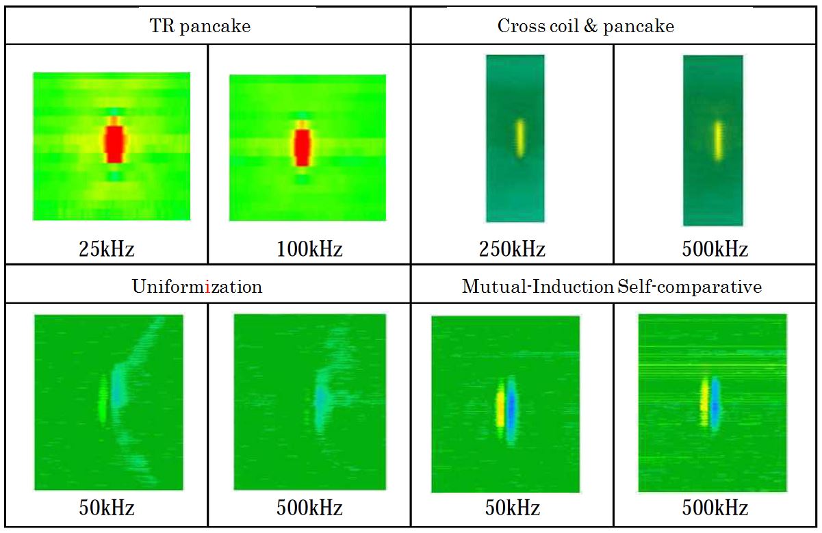
- Fig. 5-2 Example of C-scope image (mechanical fatigue flaw 1.4mm depth, 13.8mm length
The results of length measurement of all specimens by various probes are shown in Fig.6. In the case of cross coil & pancake, the length measurement by cross was implemented. Each of the results indicates that the lengths measured by 12dB drop are equivalent to effective length (around 45 degree line), measured by vanishing point are conservative (above over 45 degree line).
In the case of TR pancake and cross coil & pancake, the difference of length between by 12dB drop and vanishing point are bigger than in the case of other probes, therefore the length measured by vanishing point tends to indicate overestimate result.
-

- Fig.6 Results of length measurement by each probe
The influence of the magnetic noise was confirmed by the two combinations of probe conditions as shown below as a representative example.
a. TR pancake : 60mm length coil, frequency 25 kHz and 100kHz, V detective mode
b. Cross coil & pancake : 500 kHzThe plate specimen notched with EDM to a 1mm depth and 11.8mm length, used the unaltered part and the notched part in this confirmation and was magnetized by permanent magnet. Then the discrimination of magnetic noise and flaw signal was confirmed. In this result they were mixed on the C-scope image. The phase of the Lissajous wave indicated large difference between the EDM notch (same as calibration) and magnetic noise. It was identified that the flaw signal and magnetic noise could be distinguished by confirming the phase of flaw signal in advance.
The examples of Lissajous wave form of TR pancake and cross coil & pancake are shown in Fig.7.
-

- Fig.7 Result of confirmation test to distinguish noise
- (3) Summary of verification test results
The following results for the flaw detection of the ECT test for LAS were obtained.
- >Most of the flaws above 1mm depth could be detected by using any probe. The results of the signal combinations using the uniformization probe and the specimens with cladding were not above the threshold. But a case where they were above the threshold was observed by adjusting the scanning angle 45 degrees to the flaw.
- >Although difference in detectability depending on surface condition was not assumed, in the case of a specimen with cladding it was confirmed that the detectability was the same as in the case of LAS base material provided the scan was along the appropriate direction with respect to the flaw.
- >The accuracy of length measurement was same as in the preceding study described in JEAG4217. But some probes indicated an overestimate result in the case of measurement by vanishing point and good results by 12dB drop.
- >Although the combination of cross and pancake probes was applied for improving the detectability and showed good results, each cross and pancake probes also showed good results individually.
- >The appropriate ECT procedure for the LAS was confirmed in this study and all domestic RPV Feedwater nozzle corner ECT detectability is possible. In the event of discovery of a flaw on the nozzle corner, the integrity evaluation and consideration of the method of repair could be applied by using combination of these results and other standards already published.
- Table 4 shows the typical ECT procedure for the LAS including above results.
- Table 4 Typical ECT procedure for LAS

-
(4) Future issues
The influence of accessibility to the inspection device was not considered in this study. The inspection device in the actual plant is underwater in the RPV and there is a Feedwater Spurger as an interference. Therefore to inspect in actual plant conditions, there may be a need to make the procedure and equipment fit the layout around the part to be inspected in the each plant.
Table3 The results of flaw detection by each comvination of specimens and probes
5. Examples of Application
- Diversification of flaw detection technique of the maintenance activity including In Service Inspection in NPT.
- The application for the Special Inspection needed in the License Renewal certification guideline that was published by Nuclear Regulatory Authority in Japan.
6. Reference
- [1] Application of life extension of Takahama NPPs and Mihama NPP appendix 1 "The report of special inspection", 2015.4~2016.8, Kansai Electric Power Company
- [2] G.M. Van Dijk " Special NDT systems applied to the in-service inspection of a BWR nozzle and safe-end welds", Nuclear Engineering and Design, Volume 81, Issue 1, 2 August 1984, p.77–84
- [3] K.Ehara et. al, "Development of the Eddy Current Testing technique for the Feedwater nozzles of Nuclear Power Plant Reactor Pressure Vessels", The scientific lecture of Japan Society of Maintenology, 2016.7
- [4] Takagi et. al, "Numerical analysis of Eddy Current Testing", Journal of the Japan Society of Applied Electromagnetics and Mechanics, vol.9, No.1 (2001), p.63~64,
- [5] Japan Nuclear Energy Safety Organization, Nondestructive Inspection Technologies on the Ni Alloy Welded Joint Project Report 2009.12 p.706~909
7. Contact
Japan Society of Maintenology (ejam@jsm.or.jp)