


Internal Environment of Reactor Building at Fukushima Daiichi NPS
Classification
5 - A (Environmental improvement)
• As a part of environmental improvement inside the Reactor Buildings (hereinafter referred to as R/B) in Fukushima Daiichi Nuclear Power Station (hereinafter referred to as 1F) Unit 1 to 3, Toshiba developed various remote controlled apparatus and pursued such technology for practical use to R/B mainly in Unit 2 and 3. In this paper, the development of remote controlled decontamination apparatus and support technology for remote controlled decontamination apparatus are presented in detail.
- (1) Components:
Reactor building
- (2) Location:
Disaster site
- (3) Materials:
N/A
- (4) Condition:
N/A
- (1)Remote controlled decontamination apparatus
- Toshiba developed variety of apparatus shown in Table-1, and actually used them at 1F site since there were various types of contamination, shapes of objects to be decontaminated, and access routes to the objects to be decontaminated. Refer to the followings for Remote Controlled Decontamination Apparatus that Toshiba developed and used for 1F.
- (2)Support technology for improving decontamination efficiency
- Considering decontamination of inside R/B in 1F-1 to 1F-3 under high radiation environment, Toshiba developed supportive technology which is based on 3D CAD data composed of 3D laser-scan data, and is planning for actual use.
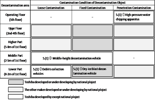
Table1 Metrics of decontamination apparatus development
5. Examples of Application
- (1)Remote controlled decontamination apparatus
- ① High-pressure water chipping apparatus
- High-pressure Water Chipping Apparatus used for decontamination of the 5th floor (Operation Floor) of R/B in 1F-3 which was hydrogen exploded. Floor concrete surface for approx. 1cm in depth was chipped by approx. 250MPa high-pressure water jet, and vacuums scraped dust simultaneously. After High-pressure Water Chipping Apparatus is lifted on Operation Floor by crane and installed, automatically its nozzle takes position under the device to perform decontamination of the bottom area by chipping. This apparatus is remotely operated, and is able to decontaminate an area of approx. 15m2 in 2 hours at one time. In addition, Toshiba prepared and applied another device for finishing vacuuming of scraped dusts on the floor which High-pressure Water Chipping Apparatus is difficult to vacuum.
- ② Remaining Debris collection vehicle
- There are many concrete debris and fine dust on the 1st floor of R/B in 1F-3 due to hydrogen explosion, and it required to remove these debris prior to cleaning with water and brush of the floor. Refer to Figure-2 for Remaining Debris Collection Vehicle for R/B. Figure on the right shows Small Debris Scraping Vehicle with a scraper and a dust box which collect debris of less than 200mm in size, and figure on the left shows Dust Vacuuming Vehicle which can be able to collect not only solid but also liquid and mud. Both vehicle have batteries and remotely controlled. Dust box is transferred by other remote controlled device.
- ③ Middle-height Decontamination Vehicle
- Middle-height Decontamination Vehicle was developed specifically to decontaminate equipment surfaces at the height of 2 to 5m on the 1st floor of R/B. Middle-height Decontamination Vehicle used on the aisle of 1st floor of R/B in 1F-2 is a small robotic device with an arm owned by TEPCO which has a mechanism to attach extendable arm at the end of its arm to wipe and vacuum. When it is used to wipe, a special mop is attached on the extendable arm, and when it is used to vacuum, a vacuuming device is installed on the rear and vacuum head and hose are attached on the extendable arm. On the other hand, Middle-height Decontamination Vehicle used for 1F-3 had two 7-axial arms at the front. As the same as the device used for 1F-2, it can not only wipe and vacuum, but also decontaminate by being able to attach Dry-ice-blast Decontamination Device described below, and remove small equipment (refer to Figure-3).
- ④ Dry-ice-blast Decontamination Device
- Refer to Figure-4 for Dry-ice-blast Decontamination Device developed by National Project. This device decontaminates efficiently by impact of dry ice blasting and by sublimation expansion of dry ice and it is beneficial since it minimizes generation of secondary waste as a result. A set of the decontamination unit, collecting device, compressor, decontamination nozzle, and the operation arm was installed on two vehicles, and they were used for R/B in 1F-2 as a trial in April, 2014.
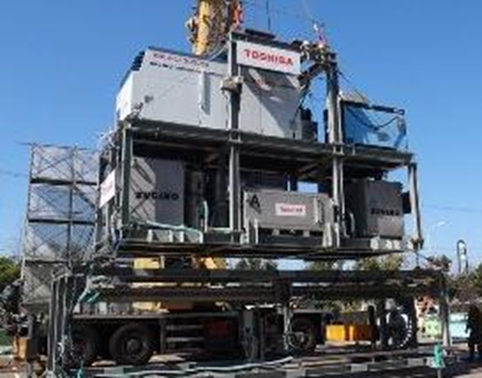
Fig.1 High-pressure water chipping apparatus

Fig.2 Remaining debris collection vehicle
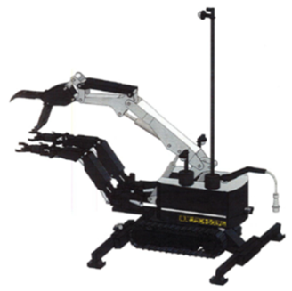
Fig.3 Middle height decontamination vehicle
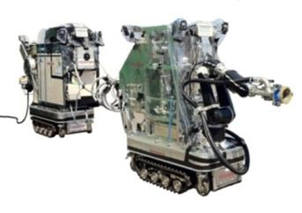
Fig.4 Dry ice blast decontamination vehicle (*)
- (2)Support technology for improving decontamination efficiency
- ① 3D measurement of high radiation area by remotely operated laser scanning vehicle
- By installing laser scanner on small remote controlled vehicle, position data while it is travelling can be acquired. Collected position data (laser scan data) are shown as dots, and distance between dots can be confirmed since each dot contains X, Y, and Z position data. Thanks to these data, accessible width for remote controlled decontamination vehicle and any objects interference with vehicle can be verified, which means that any performance by personnel under high radiation environment will no longer be required. Also this data can be used efficiently for targeted area of decontamination by selecting area beforehand (refer to Figure-5).
- ② Visualization of radiation distribution by γ camera
- Relative radiation intensity distribution of the object to be monitored can be measured by using γ camera, and by combining this evaluation result to laser-scan data mentioned above, radiation intensity distribution can be visualized. Also by acquiring data of radiation intensity in each direction of a selected area with γ camera, radiation source contributions in each direction can be evaluated for such selected area. Refer to Figure-6 for one of the example of evaluating contributions in each direction. This evaluation result can be used as the reference of the location to objects to be decontaminated. And it is also useful to plan a placement of radiation screens.
- ③ Visualization of Radiation Rate in Atmosphere
- When the environment is improved by decontamination and other relative procedure, radiation rate in the atmosphere is to be measured to make a map of radiation rate in the atmosphere. By combining this map to laser-scan data mentioned above, radiation rate distribution in the working area can be visualized, which will allow personnel to visually see and understand the area with low radiation rate to efficiently lead to, and for evacuation (refer to Figure-7).
- ④ Operation Simulation for Decontamination Vehicle
- Cruising motion of vehicle and decontamination work can be simulated by arbitrarily overlaying CAD data from decontamination vehicle on 3D data converted from laser-scan data (dots) that mentioned above. This will help us seeing interferences beforehand. Refer to Figure-8 for outline of operation simulation for decontamination vehicle.
- ⑤ Self-Position Indications for Vehicle in Motions
- Previously, positions of travelling vehicle were acknowledged by the images taken by the cameras installed on the vehicle, but it was not the best way because it depends on how well the personnel know the condition on the scene of the site. Toshiba has been trying to establish a system which will clearly indicate the current positions of travelling vehicles, by comparing and matching laser-scan data (images) to camera images installed on the vehicles. Refer to Figure-9 for indication of the current positions of travelling vehicle on laser-scan data.
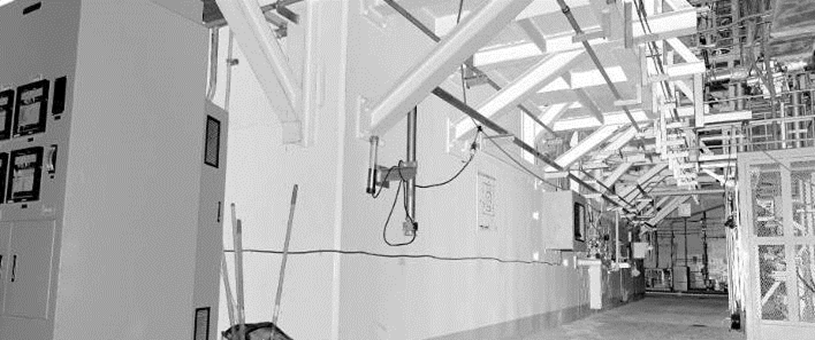
Fig.5 Example of laser scanning data
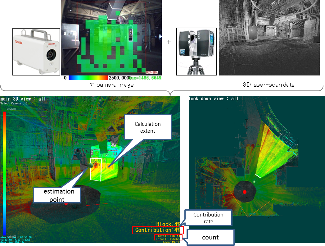
Fig.6 Example of directional dose contribution estimation by
Combining gamma camera image and laser scanning data
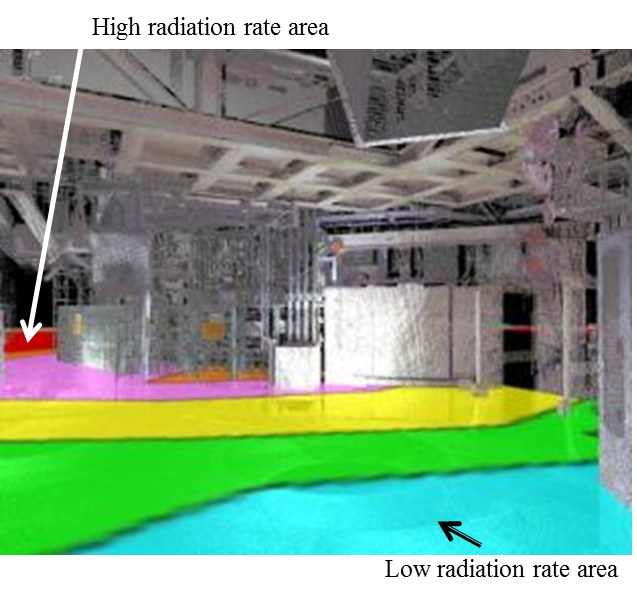
Fig.7 Combination of ambient dose rate map and laser scanning data

Fig.8 Confirmation of simulated movement of decontamination vehicle
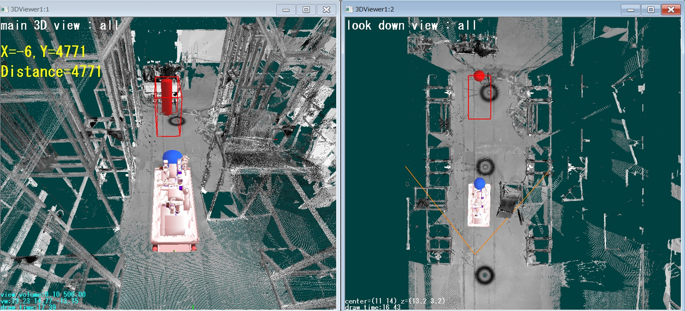
Fig.9 Vehicle position display during running*(*)
6. Conclusion
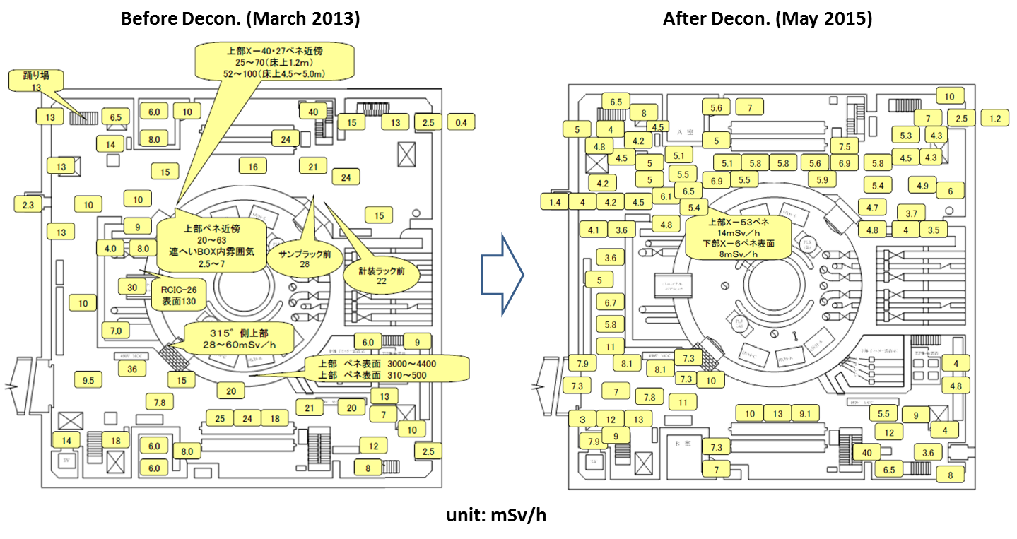
Fig.10 Pictures of decontamination effectFig.10 Reduction of dose rate of Fukushima daiichi unit2 reactor building 1st floor (**)
Decommissioning work of 1F is to safely remove fuel debris and dismantle R/B or to store under control, and it will be long term activities. Toward any kinds of requirements for environmental improvement on each of stages, Toshiba will fully make use of our knowledge and apparatus we had obtained, and proceed with decommissioning by development of technology as needed.
7. Reference
- 1.Shigeru YUKINORI, Hirofumi KINOSHITA, Hiroaki ANEGAWA, “The current situation and the issues of researches on radiation reduction and decontamination”, Atomic Energy Society of Japan, Vol. 56, No.8, 17(2014).
- 2.Hitoshi SAKAI, et al. ”Environmental improvement activities and developing technologies by TOSHIBA for Fukushima Daiichi NPS.”, Technical report of Decommissioning, No. 51, Apr.2015.
- 3.Tokyo Electric Power Company Holdings, Inc, “Application of Robot Technology”,http://www.tepco.co.jp/en/decommision/principles/robot/index-e.html
- (*)This results are achieved from the METI(Ministry of Economy, Trade and Industry)'s Decommissioning and Decontamination subsidized program of the fiscal 2014 supplementary budged.
- (**)Source : “Survey maps of Fukushima daiichi NPS” <http://www.tepco.co.jp/nu/fukushima-np/f1/surveymap/index-j.html >, Tokyo Electric Power Company Holdings, Inc
Japan Society of Maintenology (ejam@jsm.or.jp)