


Mitsubishi Heavy Industries, Ltd. (MHI)
Nuclear Plant Service Engineering Co., Ltd. (NUSEC)
Vol.9, No.4, NT88
Utilizing Examples of 3D Laser Scanning Techniques
(The updated version)
(The updated version)
KEYWORDS:
As-built Data, 3D Laser Scanner, Panoramic Photo, 3D Model, Database,
1. Technical summary
Classification
6 - A (Others)
(1) Measurement and Databasing of 3D As-built Data
3D (3-Dimensional) as-built data of components and piping that are installed at Nuclear Power Plants have been used for relocation design, piping design or work planning in remodeling works. In order to make it effective, a color 3D laser scanner with built-in digital camera (Fig.1) has been in practical use.
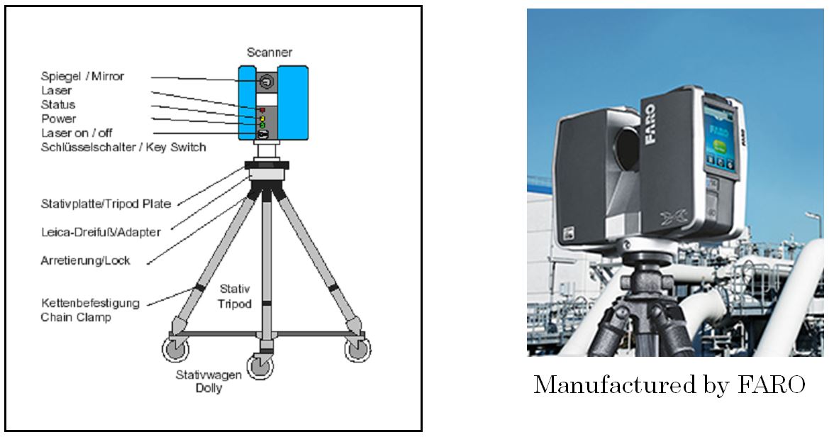
Fig. 1 Appearance of 3D Laser scanner
The as-built data is classified into two kinds of data, that are, 3D Point Group data and Panoramic Photo data from all directions (360 degree view).
Measurement of as-built data is carried out by a team of three workers. Roles of three workers are as follows; One is a supervisor responsible for the work (e.g. measurement position determination and process control) and the other two are measuring crews. It takes five to ten minutes to do laser scanning and take panoramic photos at one measurement point, which includes time to travel to the next point and set up devices. This team is able to measure 30 to 50 points a day. 3D Point Group data is a set of positional information of laser-scanned structures, which are processed into a 3D model. It requires 10 to 15 days to make a 3D model from the data measured at approximately 50 measurement points, give or take a few days depending on the conditions. For example, the content of 10 days work of 3D modeling using 3D Point Group data is as follows;
- entry of point group data (1 day)
- processing of noise removal (half a day)
- 3D modeling of point group data (7.5 days)
- integrity check of 3D models (1 day)
By superimposing the processed 3D model over a CAD model of newly installed piping or supports, the piping route plan, including consideration of interference of piping or workability of support, can be verified. This can contributes to effective designing (Fig.2). Moreover, by using the 3D modeling technique to work planning, the radiation source of high radiation area can be confirmed easily. This system can also contribute to reduction of radiation exposure of workers. In recent years, colored point group data with RGB information can be converted from measured data by using panoramic photographs taken with the camera mounted on the same axle with the laser scanner. Without using the above-mentioned 3D modeling, color point group technique can be utilized solely for piping design, and it has been contributed to improvement and high efficiency of piping design work.

Fig. 2 Example of utilization of 3D laser scanned result at Designing Section
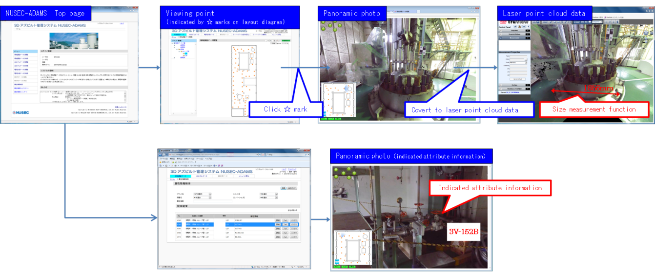
Fig. 3 user interface of 3D As-built management system
MHI has been databased locally-scanned 3D Point Group data and panoramic photos to build the system `NUSEC-ADAMS’, with which each plant data can be easily searched and controlled (Fig.3). With this system, panoramic photographs and 3D Point Group data which were photographed at the place can be easily browsed by clicking the star (★) on the display of the layout drawing. Moreover, 3D Point Group data is stored in the database after it is converted to data viewable on the intranet. Therefore, it can be shared in domestic network within a company and be linked with related system diagrams and additional information. For example, various attribute information and panoramic photographs, such as a valve number, can be linked to the data, and in the system, a panoramic photograph of the spot can be searched with its attribute information. And this system has already been applied and used by utility customers as a tool to share as-built data of the radiation controlled area in a plant between utility customers and MHI. This system has the following functions;
□ Panoramic Photo Browsing Function
- Workers can feel as if they are in the site, without actually entering there.
- Workers can accurately grasp the situation instead of relying on fallible human memories.
□ Easy Dimension Measurement Function using 3D Point Group Data
- Users can easily grasp the condition of on-site work space. (e.g. interference check of brought-in equipment)
- Users can utilize it to remodel auxiliary equipment such as scaffolding and stairs.
*The dimension is accurate in the range from 0.5 to 130 meters away from the laser scanner and the tolerance is 2 millimeters (refer to the manufacturer’s price list).
*The distance between measurement points should be within 3 meters. (Although it is only a recommended value, the measurement points should be determined not to have any blind spot.)
□ Entry and Search Function of Attribute Information
- Users can search and view panoramic pictures using attribute information.
- Users can also browse attribute information of the surrounding equipment.
(2) Application of NUSEC-ADAMS to Maintenance Activities
NUSEC-ADAMS has been applied to the maintenance planning and has increased working speed and efficiency of plant equipment installation. The following are advantages of using NUSEC-ADAMS for maintenance planning;
- Field workers can visualize the target equipment prior to field work, and reduce the time to check the equipment.
- Planning the shortest route for field work is possible by using the layout diagram linked with panoramic data.
- In case several equipment installations are carried out in parallel, interference between the installations can be confirmed in advance by using 3D Point Group data.
- With NUSEC-ADAMS, workload of scaffolding installation which is normally required for measurement of the target can be omitted. NUSEC-ADAMS has enough dimensional accuracy for preliminary study. In case the target equipment is installed in highly contaminated area, it also helps to reduce radiation exposure of workers.
- Picture data of NUSEC-ADAMS can be used for installation planning.
For instance, in case of safe-end and nozzle replacement of pressurizer (PRZ), NUSEC-ADAMS is used to plan the following items;
・location of scaffolding and Green Houses (GH*) and their assembly
・area for equipment maintenance, decontamination and storage
・control center of GH remote equipment and remote cameras
・route of utility line used for equipment, e.g. electric cables, water hoses, and air hoses
・carry-in route of new pipes with avoiding interference with concrete walls around PRZ
・simple measurement for planning of scaffolding assembly
*GH is a covered small working place to prevent spreading of contamination to the outside. - It reduces the possibility of mistakes which occur during equipment checking. (e.g. Field workers check to see if there are the same valves with the different numbers.)
In case a problem occurs during plant operation, using NUSEC-ADAMS has the following advantages;
- Since it is not possible to perform field work during operation, as-built data which is stored in NUSEC-ADAMS is a good reference to plan layout of working areas and carry-in routes.
- Pictures and related data of the equipment concerned can be seen in NUSEC-ADAMS. It improves the efficiency of equipment checking.
For instance, in case valve ground leakage or flange leakage occurs in the primary system, NUSEC-ADAMS can be used to confirm the original appearance, position, and surroundings at the time of the incident.
These advantages contribute to improve safety as well as accelerate working speed. When field operators operate equipment, as-built data of NUSEC-ADAMS decreases the possibility of human errors. If some kind of abnormality is found during operators’ walk-around, they can investigate the situation by comparing it to NUSEC-ADAMS data. In case of problems, workers (operators, field workers, engineers and related workers) can share its accurate information before the field work starts. It also helps to improve the quality of decision making.
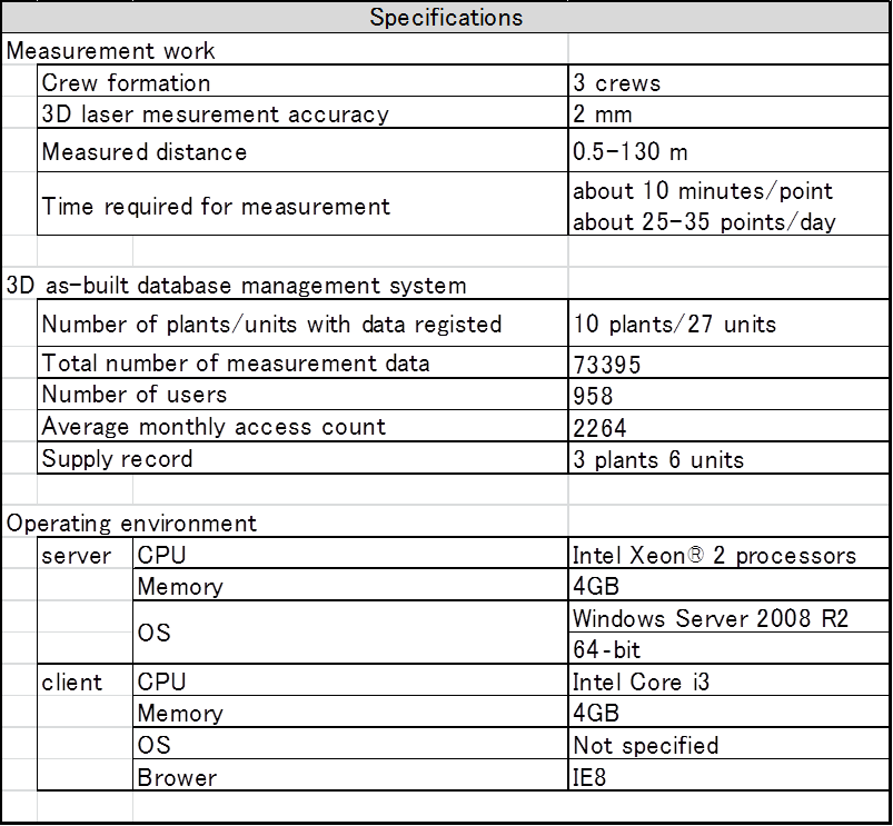
Tab.1 Specification table of 3D Laser scanning technique
2. Development Phase
Phase 3: Authorities’ Approval Phase
This technique has been applied to remodeling work of piping and support in Japan since 2006.
3. Scope
- (1) Components:
SSC (Structures, Systems and Components) of Nuclear Power Plant
- (2) Location:
Anywhere
- (3) Materials:
Regardless of material
- (4) Condition:
in the Atomosphere
4. Features
- Panoramic photos, 3D Point Group data and 3D models are all available in integrated management system.
- Target objects can be retrieved as well because property information and 3D models are linked to the objects.
- Utilizing this system over a wide range of maintenance activities, images of the whole construction can be visually shared among stakeholders.
- Even during plant operation, maintenance planning and troubleshooting can be smoothly carried out.
- Radiation exposure of workers can be reduced.
5. Example of Application
This system has been applied to CV and Loop areas of nuclear power plants since 2006.
6. Reference
- 1.T. Maruyama, The Situation of the Earthquake-Proof Reconstruction Construction using Laser Measurement, Society of Maintenology 6th Meeting, August 3-5, 2009
- 2.K. Okimura, T. Kobayashi, T. Tsuruta, J. Nishitani, M. Toyoda, MHI’s Maintenance Technologies Supporting High Plant Availability of PWR Nuclear Power Plants, Mitsubishi Heavy Industries Technical Review Vol.47 No.1, March, 2010
- 3.August , 2012 E-JAM Vol.4 No.2 , Utilization Examples of 3D Laser Scanning Technique
- 4.Kazutaka Okumura, Maintenance Services of Nuclear Power Plant Using 3D As-built Database Management System, April, ICAPP 2017
7. Contact
Japan Society of Maintenology (ejam@jsm.or.jp)