Kazuki Ikushima*, Masakazu Shibahara*, Satoru Nishikawa**, Takashi Furukawa**, Koichi Akita***, Hiroshi Suzuki***, Satoshi Morooka***
*Osaka Prefecture University
**Japan Power Engineering and Inspection Corporation
***Japan Atomic Energy Agency
Shot peening, Residual stress, Multi-pass welding, Non-linear analysis, Finite element analysis
1. Technical summary
Classification
3 - C
It is known that residual stresses affect the occurrence of stress corrosion cracking (SCC) and fatigue crack (FC). These defects may have an influence on the occurrence of severe accidents. So, to ensure structural integrity to avoid severe accidents, the residual stress distribution should be investigated in advance of the production. In steel structures, welding is widely utilized as a production method to join structural members, and it inevitably causes residual stresses. Thus, various peening techniques such as shot peening, laser peening, water jet peening and so on, have been proposed to reduce or mitigate the tensile residual stress after welding. In these methods, an impulsive load is applied to the surface of the target, and compressive residual stresses are introduced. The effect of the peening technique is investigated in various reports [1–3]. However, to investigate its effect on the prevention of SCC or FC, it is important to consider the behavior of the stress distribution modified by peening on the operation. This requires a prediction of the stress distribution after peening; thus, numerous impact loads must be considered in the prediction.
To predict the effect of modifying the residual stress distribution by peening using FEM, an extremely detailed spatial resolution that can analyze the behavior of the peening process is required. Therefore, the number of computations becomes significant, and it is difficult to perform the analysis using conventional methods such as commercial FE software. In addition, for example in shot peening, assuming numerous shot collisions, tens of thousands or more collisions should be considered to simulate the change of stress distribution on peening surface. This leads to a further increase in computational time. Moreover, to discuss the modification of the welding residual stress, the welding residual stress must be investigated in advance, which would make the analysis more difficult.
On the other hand, the authors have proposed Idealized Explicit FEM (IEFEM) [4], which can predict the welding residual stresses and the deformation of practical structures in realistic computing time. In IEFEM, convergence to a static equilibrium state is considered, although IEFEM is based on dynamic explicit FEM [5]. Thus, it can obtain an accurate solution with shorter computational time and memory consumption. In addition, since IEFEM is based on dynamic explicit FEM, IEFEM is highly suitable for parallelization. By using parallelization with a graphics processing unit (GPU), IEFEM can achieve even faster computation and the residual stress distribution in multi-pass welded pipe was predicted [6].
In this work, an analysis system that can analyze the modification of the residual stress distribution by peening is proposed based on IEFEM. In the proposed analysis system, IEFEM is extended to consider the dynamic effect to analyze the dynamic phenomenon with an impulsive load. The impulsive load due to the collision of shots is modeled as an equivalent load model. The equivalent load model is integrated with IEFEM considering the dynamic effect to calculate spatially and temporally random load in dynamic analyses. Using the proposed analysis system, the residual stress distribution modification by shot peening in a multi-pass welded pipe joint is predicted. The residual stress distributions obtained by the analysis are compared with those measured by X-ray diffraction (XRD), and the effect of the number of shot collisions on the change in residual stress distribution is discussed.
2. Development Phase
Phase 1 : Research and Development Phase
3. Scope
4. Features
In shot peening, 1 mm or smaller shots collide with the target surface numerous times and compressive stress is introduced. To predict the stress distribution under such a process, dynamic elastic plastic analyses with extremely high spatial resolution are necessary. Here, the proposed analysis system that can predict the residual stress distribution after shot peening by using the large-scale nonlinear mechanical analysis method named IEFEM [4], is briefly explained. The detailed formulations are found in the literature [7].
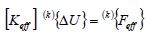
In dynamic elastic plastic analyses using IEFEM, the semi-discretized equation of motion by FEM is discretized for time by using Newmark’s beta method and is linearized by the Newton-Raphson method. Equation (1) is defined as the fundamental equation:
 (1)
(1)
where ,
,  , and
, and  are the effective stiffness matrix, the displacement increment vector, and the effective load vector, respectively. The left superscript (k) is the iteration number in the Newton-Raphson method.
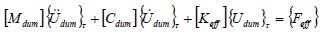
Adding the virtual inertial term and the virtual damping term yields the following equation:
 (2)
(2)
where  and
and  are the virtual mass matrix and the virtual damping matrix, respectively.
  ,
,  , and
, and  are the acceleration vector, the velocity vector, and the displacement vector at virtual time , respectively. The displacement vector is defined as
  .
.
Discretizing Eq. (2) by the central difference and advancing the time steps until the virtual inertial term and the virtual damping term become negligibly small, that is, advancing the virtual time  in Eq. (2), enables the displacement vector to be obtained. The displacement vector obtained by advancing the virtual time is used as a solution. By using these steps, it is expected that the same solution as that by solving Eq. (1) using the iteration method (Newton-Raphson method) can be obtained. The virtual mass matrix and the virtual damping matrix are utilized only to obtain the converged solution. The formulation of these matrices, which can reduce the number of time steps for convergence, are employed as shown in [8].
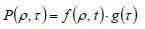
A load on the collision of a shot is considered in the above dynamic elastic plastic analysis method based on IEFEM, and the analysis system of the mechanical behavior during shot peening is constructed. As shown in Fig. 1, the history of the load distribution during the collision of a shot is modeled as an equivalent load model [7], which is introduced as an external force. The equivalent load model is expressed as the product of the load distribution function defining the shape of the load distribution, and the load history function defining the amount of the colliding load as shown in the following equation:

Fig. 1 Schematic illustration of equivalent load model for shot collision
 (3)
(3)
where , and
, and  are defined as the normalized distance from the collision center, the normalized time from the beginning of the collision, the load distribution history function, the load distribution function, and the load history function, respectively. Here,
  and are defined as follows:
 (4)
(4)
where  and
and  are the distance from the collision center and the shot radius, and
  and
and  are the time from the beginning of the collision and the duration of the collision, respectively. The load distribution function and the load history function are defined as the functions that can reproduce the reaction force distribution obtained by the analysis of the collision of a single shot considering contact.
・5. 1 Analysis model and conditions
The effect of the modification of the residual stress distribution in a multi-pass welded pipe is investigated. The analysis model is shown in Fig. 2. A mockup is also prepared to measure and compare the residual stress distribution. The analysis model is meshed using hexahedral elements. The number of nodes and elements are about 3.5 million and 3 million, respectively. The procedure of this analysis is as follows: First, the welding residual stress is predicted using the quasi-static thermal elastic-plastic analysis method based on IEFEM [6]. Next, the elements of the inner and outer regions (which are removed by machining) are deactivated, and the redistribution of stress is calculated. Then, the shot peening process is analyzed by the proposed analysis system, and the modification of the stress distribution due to shot peening is investigated.
Regarding the thermal elastic plastic analysis of welding residual stress, the temperature-dependent material properties of the pipe (SUS316L) and weld metal (Y316L) are assumed as shown in Figs. 3 and 4, respectively. The number of welding layers is 10, and the number of welding passes in each layer is 1. The welding method is tungsten inert gas (TIG) welding. The same welding conditions are used for all of the welding passes. The welding conditions are as follows: current = 180 A, voltage = 10 V, speed = 10 cm/min, and heat efficiency = 0.8. The work hardening rule employed in this analysis is bilinear isotropic hardening. The annealing effect is modeled by setting the equivalent plastic strain of an element to zero at temperatures higher than 850°C [9].

Fig. 2 Analysis model
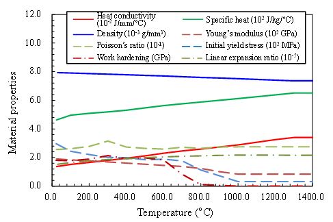

Fig. 3(Left) Temperature-dependent material properties of base metal (SUS316L)
Fig. 4(Right) Temperature-dependent material properties of weld metal (Y316L)
Regarding the analysis of the shot peening process, shot peening is conducted on the outer surface of a pipe after machining, as shown in Fig. 2(b). The effect of cutting work is not directly modelled in the analysis since the affected layer due to cutting is smaller than that of shot peening [10]. The region on which shot peening is performed is assumed to be a range of 70° in the hoop direction from 145° to 215° from the starting point of welding. In addition, the shot peened region is meshed with 0.2 mm cubic hexahedral elements, as shown in Fig. 2. The ratio of the collision area (on which the load is applied by the equivalent load model) to the area of the shot peened region, which is defined as the collision area ratio Rc, is defined by the following equation:
 (5)
(5)
where A, , and S are the loaded area at a collision, the collision count, and the area of the shot peened region, respectively. In this analysis, shot peening is performed until Rc reaches 50.0, which is assumed to be a sufficiently large ratio. The specification of the computer employed in this analysis is as follows: an Intel Core i7 3.5 GHz processor, 64GB of RAM, an NVIDIA GeForce GTX TITAN GPU.
・5.2 Predicted residual stress
The proposed analysis system can analyze 3 dimensional stress distributions. In this section, axial stresses are discussed as an example.
Fig. 5 shows the distribution of stress in the axial direction  at the cross section 180° from the welding starting point for the as-machined state (Rc=0.0), Rc=10.0, Rc=25.0, and Rc=50.0. The dynamic effect is considered in this analysis, so the stress distribution obtained by the proposed analysis system contains the dynamic effect, such as the inertial term. Therefore, to remove the dynamic effect from the stress distribution, quasi-static elastic plastic analysis is performed after each Rc is reached. This is to simulate the shot peening finishes after each Rc is reached. As shown in Fig. 5, the outer surface has compressive stresses at the as-machined state near the welded part. In this case, due to the arrangement of experimental apparatus, shot peening was carried out to the outer surface. From Fig. 5, it can be seen that the stress at the outer surface is small for the as-machined surface, and larger compressive stresses are found at Rc=10.0 (b), Rc=25.0(c), and Rc=50.0(d).

Fig. 5 Axial stress distribution at the cross section 180° from the welding starting point
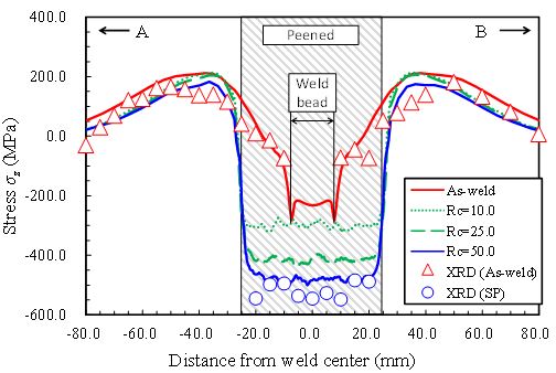

Fig. 6(Left) Comparison of axial stress distribution between analysis and XRD along line A-B
Fig. 7(Right) Comparison of axial stress distribution between analysis and XRD along line C-D
Fig. 6 shows the distribution of stress in the axial direction along line A-B. In the figure, the red solid line shows the welding residual stress (as weld). The green dotted line, dashed line are the stresses at Rc=10.0, 25.0, respectively, and the blue solid line is those at Rc=50.0. The red triangles and blue circles are the stresses measured by XRD after welding and shot peening, respectively. From Fig. 6, it can be seen that the as-weld residual stresses obtained by the analysis agree very well with those by XRD. It is also found that difference between the stress distribution at as-weld and that at Rc=10.0 is large, and with the increase in Rc, the compressive stress in the peening region becomes larger. Regarding the stress distribution in the peening region, the stress distribution at Rc=50.0 can reproduce the measured values well. It can also be seen that the change in the stress distribution is large in the peened region, and the change is small in the other region.
Fig. 7 shows the distribution of stress in axial direction along line C-D, which is cut-through thickness direction. In these figures, the green dotted line, dashed line, and the blue solid line are the stresses at Rc=10.0, 25.0, and 50.0, respectively. To show the change of the stress distribution in cut-through thickness direction due to the progress of shot peening, the shot peened stresses are compared with those at as-machined (Rc=0.0) which is shown as the red solid line in Fig. 7. From this figure, it is found that the difference between the shot peened stress distribution and the as-machined stress distribution is larger with the increase of Rc. It can also be seen that the shot peened stress distribution gets closer to the as-machined stress distribution in the distant region from the outer surface and the difference between these distributions becomes almost zero at 7mm from the outer surface.
As shown in this chapter, the shot peened stress distribution can be predicted by using the proposed analysis system and the analysis finished within the realistic computing time of 10 days. These kinds of simulation are very difficult with conventional method such as commercial FE software because of its unrealistic computing time. In addition, it can be expected to contribute to the further accurate evaluation of FC or SCC by considering the predicted residual stress distribution.
・Acknowledgement
A part of this work is the result of “Development of a basic technology for the safety assessment of residual stress improvement method on nuclear power plant structures” carried out under the Center of World Intelligence Project for Nuclear S&T and Human Resource Development by the Ministry of Education, Culture, Sports, Science and Technology of Japan.
7. Contact


