


| Vol.1 No.4 |
|||||||||||||||||||||||||||||||||||||
| Vol.2, No.1, NT22
|
|||||||||||||||||||||||||||||||||||||
A Monitoring System for Condition-based Maintenance without Laying New Communication Cables |
|||||||||||||||||||||||||||||||||||||
| TOSHIBA Corporation |
|||||||||||||||||||||||||||||||||||||
KEYWORDS: |
|||||||||||||||||||||||||||||||||||||
| 1. Technical summary | |||||||||||||||||||||||||||||||||||||
| Classification (I: Inspection, II: Repair, III: Replacement, IV: Preventive Maintenance, V: Others) | |||||||||||||||||||||||||||||||||||||
|
By applying condition-based maintenance (CBM), monitoring points are expected to be increased. Toshiba developed a new monitoring system used for condition-based maintenance (CBM) with minimal cost. This system allows plant personnel in the control room or plant office to monitor plant equipment by video images and real-time sensing data, such as vibration, without laying new communication cables. Figure 1 shows the system configuration. The system uses existing device control cables for data transmission. The transmitter modulates the video or sensing signals, and superimposes the modulated signals on the device control signals over the existing cables; the receiver separates the modulated signals from the control signals, and demodulates the signals. The system analyses the video images and sensing data, such as vibration, and detects abnormalities of rotating machines, valves, or piping. This system supports plant equipment integrity by early detection of abnormality, and eventually contributes to maintenance cost reduction.
.png) Fig.1 System configuration
.png) Fig.2 Block diagram of the monitoring system
| |||||||||||||||||||||||||||||||||||||
| 2. Scope | |||||||||||||||||||||||||||||||||||||
(1) Components
Plant equipment (Rotating machines, valves and piping, etc) (2) Condition Existing cables such as the control cables and the switching cables can be used for transmission of monitoring data. | |||||||||||||||||||||||||||||||||||||
| 3. Features | |||||||||||||||||||||||||||||||||||||
(1) Existing cables are used for transmission of monitoring data.
The monitoring data is transmitted to the office or control room, by just connecting the transmitter and receiver with existing cables. (2) Various monitoring devices can be connected to the system, for examples; ・Video Camera (with direction control) ・Vibration transducer (accelerometer, proximity probe, etc) ・Process sensors (pressure gage, flow meter, etc) ・Any sensors that provide voltage outputs (3) The transmitter and receiver are designed not to influence the control signal or switching signal. The level of modulated signals is sufficiently low compared with the control signal as shown in Figure 4. (4) The signal transmission doesn't influence instrumentations because electric field strength caused by monitoring signal transmission is below a regulated value, VCCI-class A. VCCI: Voluntary Control Council for Information Technology Equipment Figure 1 shows the transmitter, network camera, and wireless accelerometers. Specification of each device is shown in Table 1. 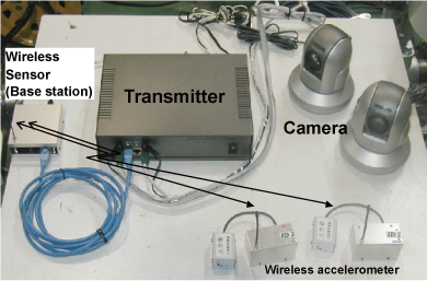 Fig.3 Transmitter, cameras and sensors
Table 1 Specification of transmitter, receive and sensors
.png) Fig.4 Waveform of l transmission signal
| |||||||||||||||||||||||||||||||||||||
| 4. Examples of Application | |||||||||||||||||||||||||||||||||||||
|
Examples of application are shown below.
(1) Figure 5 shows an example, where signals are transmitted over a limit switch cable of a motor operated valve (MOV) installed in a plant test loop. Video image and vibration data are transmitted with satisfactory quality and response time. Figure 6 shows sample video image. In the actual system, an operator can control camera angle and zooming, to confirm the meters and leaking point. The applicability evaluation to the actual plant is planned in the near future. .png) Fig.5 Signal transmission using MOV switch cable
.png) Fig.6 Sample of video image
(2) Condition monitoring equipments in Pressure Containment Vessel (PCV) of nuclear plants (Figure 7) The monitoring signals can be transmitted without using additional electrical penetration assembly.
.png) Fig.7 Condition monitoring of equipment in PCV
|
|||||||||||||||||||||||||||||||||||||
| 5. Reference | |||||||||||||||||||||||||||||||||||||
| [1] K.OSAKI, et al., "Development of the monitoring system using existing cables and wireless sensors", Proceedings of the 2nd Annual Meeting, Japan Society of Maintenology, 2005 (in Japanese) |
|||||||||||||||||||||||||||||||||||||
| 6. Contact | |||||||||||||||||||||||||||||||||||||
| Japan Society of Maintenology (ejam@jsm.or.jp) | |||||||||||||||||||||||||||||||||||||
|
Vol.10 No.2(Aug) |
|
| < Other Issues | |
|---|---|
 |
A New Mechanical Condition-based Maintenance Technology Using Instrumented Indentation Technique |
 |
Survey robots for Fukushima Daiichi Nuclear Power Plant |

Contacts
(EJAM): ejam@jsm.or.jp
(JSM): secretariat@jsm.or.jp
HP: http://www.jsm.or.jp
(in English)
![]()