


| Vol.1 No.2 ← GA 6 - 7 - AA 8 - 9 - NT 10 - 11 - 12 - 13 → Vol.1 No.3 |
| Vol.1, No.3, NT11
|
RESIDUAL STRESS IMPROVEMENT FOR NICKEL BASED ALLOY PWSCC MITIGATION BY ULTRASONIC SHOT PEENING |
| MITSUBISHI HEAVY INDUSTRIES, LTD. |
KEYWORDS: |
| 1. Technical summary |
| Classification (I: Inspection, II: Repair, III: Replacement, IV: Preventive Maintenance, V: Others) |
| (1)Ultrasonic Shot Peening (USP) is a kind of shot peening method. Piezoelectric element is used for an ultrasonic vibrator instead of an air/water drive source of a conventional one. |
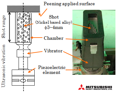 Fig.1 Principle of USP |
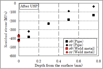
(2)The improvement of surface residual stress is effective in prevention of stress corrosion cracking (SCC) initiation due to tensile residual stress. |
_A_typical_residual_stress_distribution_before&after_USP(Sample-piece).png) Fig.2a A typical residual stress distribution before/after USP (Sample piece) |
 |
|
|
|
| 2. Scope |
(1) Components: Steam Generator (SG) of PWR and
Reactor Vessel (RV) of PWR (2) Location: SCC susceptible zone of SG and RV (3) Material: Alloy 600/690 (Nickel based alloy) and Austenitic stainless steels of SCC sensitizes zone (4) Condition: This method can be applied to components under atmosphere. |
_USP_applicable_location_of_Steam_Generator(SG)_of_PWR_plant.png) Fig.3a USP applicable location of Steam Generator (SG) of PWR plant |
_USP_applicable_location_of_Reactor_Vessel(RV)_of_PWR_plant.png) Fig.3b USP applicable location of Reactor Vessel (RV) of PWR plant |
| 3. Features |
(1) Residual stress improvement depth by USP is deeper than the conventional shot peening, because the ultrasonic vibration and large diameter shots can be applied. (2) Mitigation of PWSCC propagation (3) Reduction of personnel dose rate by the remote operation (manipulator) (4) Lost parts management is easy because of working in the chamber and using larger diameter shots compared with the conventional shot peening. (5) Application to complicated geometry is possible, since the suitable construction range is wide. |
| 4. Examples of Application |
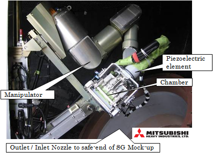
| (1) Outlet / Inlet Nozzle to safe-end weld of SG of PWR (more than 10 PWR plants) (2) Outlet / Inlet Nozzle to safe-end weld of RV of PWR (only under construction) (3) CRDM* Nozzle to Vessel Head J-weld of PWR (several PWR plants) |
Fig.4b Demonstration of USP (in Visible Chamber) |
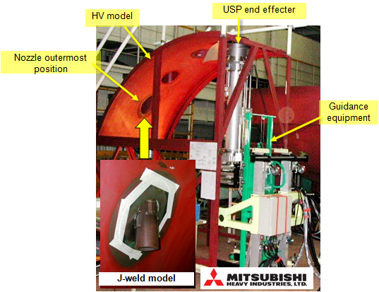 Fig.4c USP equipment for J-weld of CRDM Nozzle to Vessel Head |
| 5. Reference |
| PWSCC Preventive maintenance Program for ALLOY 600 ICONE16-48378 (2008) |
| 6. Contact |
| Japan Society of Maintenology (ejam@jsm.or.jp) |
|
Vol.10 No.2(Aug) |
|
| < Other Issues | |
|---|---|
 |
A New Mechanical Condition-based Maintenance Technology Using Instrumented Indentation Technique |
 |
Survey robots for Fukushima Daiichi Nuclear Power Plant |

Contacts
(EJAM): ejam@jsm.or.jp
(JSM): secretariat@jsm.or.jp
HP: http://www.jsm.or.jp
(in English)
_A_typical_residual_stress_distribution_after_USP.png)
![]()